Mr Icebear
I conected the sheilds under the board to the cap legs. As far as improvements
my impression is that it sounds "smoother" but thats what I was expect so
maybe it is a placebo effect. I also recently have made other changes in my
system recently so my subjective judgements will be a bit off.
I have the stock caps on the input and think the effect of sheilding maybe less
profound than it could be with physically larger input caps. All and all without
measurements all I can say is that my impresion is that it sounds smoother
with a slight widening of the sound stage.
Just thought I'd get back to this shielded coil idea, as I was doing some tests recently.
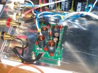
In the Trends amp there is a pair of aircore coils that is right against one of the input caps. The coils should be radiating a lot of noise into that cap. Certainly the input cap will pick up hum and buzz if you put a finger on it (not unique to the Trends). And it is easy to see a nice square wave on the o'scope when the scope probe is brought near the coils.
So I rigged up a grounded shield that could be slid in and out of place around the coils. This could easily be done while listening to the amp.
Could I hear the difference? Yes. Could I measure it? No.
I looked at the noise on the input caps, thinking that the shield around the coils would reduce RF noise. As far as I could see on the scope, it did not. There is plenty of RF noise all over the place in a Tripath amp, so it wasn't hard to find it on the input circuit right at the caps. But there was no visible change in the amplitude, phase or appearance of the noise as the shield was slid on and off.
Checking the outputs, there was slightly more RF with the shield in place - just a tiny amount.
Very disappointing. Can't measure it at all - at least not with the oscilloscope. But I could hear it. The sound with the shield seemed smoother, calmer, less artificial. Removing the shield always had the same effect. At first it would sound like a little more treble or detail, but after a few seconds started to sound more like grain or distortion. This was particularly noticeable on vocals.
So what's going on? The effect is subtle, to be sure, but seems real. Can not see it at all on the scope.
In a related event, I have a prototype amp that kills my FM tuner. It's blasting RF out of the speaker cables. But it measures lower than other amps on the scope! Of course the scope is just showing the ~1MHz fundamental and some fuzzy harmonics. They are lower than most T-Amps I've worked with. But the signal strength meter on my tuner goes from almost zero to 4/5 when the amp is on, even the stereo light comes on! So there is a lot of high harmonic energy that isn't obvious on the scope. (Need to borrow another spectrum analyzer).
Could there be some RF energy getting into the caps and then the amp inputs that can not easily be seen? Would that be the cause of the grain of roughness without the shield?
Comments? Ideas?
Shielding with ERS paper did help a lot in my Trends amp, without I even couldn't listen to these amps, realy very harsh and over exagerated highs. Inititally I shelded the complete inside of the amp and the output coils and put some directly on the chip as well. Weel that was a bit of a mistake. I have done this experiment in a couple of other equipment but everytime I put the ERS paper directly on the active components things get only worse, ikt sucks the life out of the music. Don't ask me why, I really haven't got a clue why this stuff works that way but that is does something that's clear to me.
In the end I also removed the ERS from the sides of the case so there's only some left on the top and the bottom of the case wich seems to work best.
I have also tried some ERS shielding on the power supply and on the powercables but couldn't hear any effect.
In my attempt to improve the Trends TA10 I'm still thinking about transformer coupling of the input instead of the coupling caps to keep common mode RFI/EMI problems to a minimum, still have to figure out the proper way to do it.
Yes, noise is a problem. I think it contributes to harshness. Kill the noise, kill the harshness.
And it may be a problem with the components upstream from the amp. If the RF noise on the input lines is getting back into them and causing a problem, that could lead to bad sounds. I do know that the RF noise travels out of the amp and into other connected components.
Thanks for reminding me about transformers. It's something I've been meaning to do for a long time. I'll dust off some transfos that are on the shelf and have a listen.
For simple RF blocking and ground loop break, they could be mounted outside of the amp, before the RCA connectors. For example in a separate box. A fast fix, no mods needed. I used to have some big old line transformers like that for P.A. use. They could really clean things up in a big concert rig.
Speaking of which, in North America you can go to Radio Shack and pick up a Ground Loop Isolator Catalog #: 270-054. Not the worlds best transformer, not Hi-Fi - but at $17 it might be interesting to try. It should reduce the RF by a large amount, as well as isolating the ground.
I read this thread with interest and thought I'd try shielding the chip in my amp6 basic.
I used come induction loop copper tape I had spare and the result seems very good at this early stage: definite decrease in harshness and listening fatigue, without any loss of detail to my ears....
Well worth a try")
I used come induction loop copper tape I had spare and the result seems very good at this early stage: definite decrease in harshness and listening fatigue, without any loss of detail to my ears....
Well worth a try
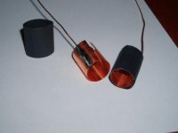
Hi, maybe an added safety to the original idea... I used 0.15 mm copperfoil. Cut a stip of 2 cm wide and appr. 3 cm long. Bent it around a bar appr. 2 cm in diameter. In every tools box you can find one. Soldered a piece of wire on the copper foil. Made it so that the copperfoil circle neetly fits a 19mm insulating and shrinking tube so that there is a little overlap in the copperfoil so that if shrunk the tube with a little hot air the copperfoil also shrinks. The tube should be a little bit longer than the copper as not short circuit some connection on the pcb.
Every air core receives its shielding and the wires can be grounded on the board, voila.
Every air core receives its shielding and the wires can be grounded on the board, voila.
Attachments
- Status
- This old topic is closed. If you want to reopen this topic, contact a moderator using the "Report Post" button.
- Home
- Amplifiers
- Class D
- Shielding the Charlize