I'm looking for a new technique for chassis construction that will offer better shielding than I currently am achieving as I embark on some preamp projects.
My current technique is sort of a modified top plate: a 3 piece glued wood front + sides, an aluminum top plate and aluminum back plate. I use aluminum because my shop is not so well equipped, and I need the softness of aluminum to get a tight fit on non-round fittings such as IEC sockets. I try to use spacing and orientation to get as much isolation between the power and signal side as possible. I use DC for heaters.
I am thinking of adopting a combination chassis: a commercial steel enclosure for the PS attached to a commercial aluminum enclosure for the signal circuit. Holes with grommets would allow power (only DC) to pass onto the signal side from the PS side.
The drawbacks as I see them are dealing with cuttouts for the abovementioned IEC socket in steel and galvanic corrosion (hardly a concern for me).
Any experience to pass on or pitfalls to my plan?
I use the steel chassis from Hammond. If you can find greenlee punches, especially the iec socket punch for less then a small fortune then your golden. Currently, I outline the shape, drill out as much as I can, and then file it to shape. This technique sucks, but it works. I used hole saws with drill bit guides for my last project, this sucked as well, but also worked. I have my amp in the middle of all my other gear and I get no cross talk or interference so I would say I find it well shielded.
Why not try a commercial aluminum chassis for the power supply as well ? With seperate chassis you may be able to position your power supply so that magnetic coupling to the amplifier section is not a problem. ( I am assuming magnetic sheilding is why you want steel for the power supply chassis , or was it a matter of heavier components eg transformers in the power supply ?).
Lead Belly,
I use a "similar" method to the one you are using as far as wood and aluminum. What I do is use copper clad PC board. I prefer the kind with copper on one side only. I affix the PC board to the underside of the "top plate" of veneered plywood temporarily while making "pilot" holes for the sockets etc that pass thru to the top. Then with them separate I can clearance the top plate of wood with larger holes and the copper clad for the sockets.
Since you are using DC on the filaments also I suspect that possibly your noise is not from the PS components but possibly from Ripple on the DC. What type of rectification and regulation are you using on the filament supply? I went to DC on a Preamp project and it was NOISIER than the AC because of lack of ripple rejection and too little filtering.
Unless you plan to run the preamp on a boat at the ocean I highly doubt that galvanic action will be an issue with steel and aluminum chassis, but it seems to me that you are going through a lot of trouble to eliminate noise that might not be caused by what you think.
The method of PC board and wood works quite well and allows me to place grounds any where I want as well as providing a "clean" look on the underside.
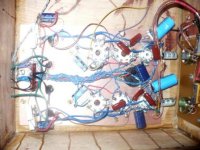
Attached is a picture of the "amp" section of my 6V6PP. This was my first attempt with the wood and PC board construction. One nice feature is this.
By minimizing the "external" connections of the "board" to the PS and input you can remove the board from the amp chassis and make changes on the bench without all the chassis and things in your way. For instance this amp has only a ground, B+, signal and 6 OPT wires to "remove" then with a few screws I can take the entire "amp" out of the chassis and do what I want.
I use a "similar" method to the one you are using as far as wood and aluminum. What I do is use copper clad PC board. I prefer the kind with copper on one side only. I affix the PC board to the underside of the "top plate" of veneered plywood temporarily while making "pilot" holes for the sockets etc that pass thru to the top. Then with them separate I can clearance the top plate of wood with larger holes and the copper clad for the sockets.
Since you are using DC on the filaments also I suspect that possibly your noise is not from the PS components but possibly from Ripple on the DC. What type of rectification and regulation are you using on the filament supply? I went to DC on a Preamp project and it was NOISIER than the AC because of lack of ripple rejection and too little filtering.
Unless you plan to run the preamp on a boat at the ocean I highly doubt that galvanic action will be an issue with steel and aluminum chassis, but it seems to me that you are going through a lot of trouble to eliminate noise that might not be caused by what you think.
The method of PC board and wood works quite well and allows me to place grounds any where I want as well as providing a "clean" look on the underside.
Attached is a picture of the "amp" section of my 6V6PP. This was my first attempt with the wood and PC board construction. One nice feature is this.
By minimizing the "external" connections of the "board" to the PS and input you can remove the board from the amp chassis and make changes on the bench without all the chassis and things in your way. For instance this amp has only a ground, B+, signal and 6 OPT wires to "remove" then with a few screws I can take the entire "amp" out of the chassis and do what I want.
Attachments
Robert McLean said:I am assuming magnetic sheilding is why you want steel for the power supply chassis
Yes.
My latest 'junk-box' project was made on a Plastic box, and I'm quite pleased with it as its only cost a couple of quid to do......
Its stereo power-amp based very basically on a David-Berning screen-drive amp. Valve line-up is-
Gain stage, 6SL7GT.
Phase-splitter, 6SN7GT,
Second gain-stage, 12AT7
MOSFET screen-drive stage, with independant bias adjustments
Output pair, 12GE5 'sweep-tubes' running at 3mA idle-current
The tranformers were rescued outta a defunked Heathkit amp rated for around 12W per channel.
All point to point, transformers and valve sockets mounted directly onto the plastic, but each metal item has a grounding-lead back to the centre-point of the full-wave centre-tap of the transformer.
I use AC heating, but biassed to +45V (Without this, Hum is intolerable....)
There is No Hum or any 'picked-up noise' when this amp is running. Not even when you stick your head right up to the speakers....
--Guess what I'm trying to get at, Shielding is Good, BUT Don't Rely on it Completely, Good circuit Layout and design are more important than just shielding.....
--Guess what I'm trying to get at, Shielding is Good, BUT Don't Rely on it Completely, Good circuit Layout and design are more important than just shielding.....
I concur! That was what I was pointing at. Without the specifics as far as the DC supply we can't be sure that the noise is coming from the Magnetics.
coldcathode said:I concur! That was what I was pointing at. Without the specifics as far as the DC supply we can't be sure that the noise is coming from the Magnetics.
Frankly, all of your posts are of little value to me. I am grateful for you to pass on advice and experience and I thank you very much for that. If you all prefer to address shielding/hum issues by layout or whatever, that is just great. I however proposed an idea for what I am hoping is so robust a technique that it will leave me much more freedom in building, and I am specifically looking for a technically supported critique of that. TIA.
Leadbelly,
A "technically supported" critique of what? Using Steel chassis? Been done for years.
Using aluminum chassis? also been done for years?
All we are getting at is NO TECHNICAL details have been offered to critique!
Give us an EXAMPLE of why you think your current technique is sub-par to your proposed technique!
If shielding the PS from the Signal circuits is important why not separate them altogether onto separate chassis and shield them with 2 inches of lead?
I am just trying to prevent you from chasing down a gremlin that might not be worth chasing in the end. Unless you can verify the negative effects of the MI then why try to mitigate them?
coldcathode said:A "technically supported" critique of what?
Once again:
I am thinking of adopting a combination chassis: a commercial steel enclosure for the PS attached to a commercial aluminum enclosure for the signal circuit. Holes with grommets would allow power (only DC) to pass onto the signal side from the PS side.
coldcathode said:All we are getting at is NO TECHNICAL details have been offered to critique!
Once again:
I am thinking of adopting a combination chassis: a commercial steel enclosure for the PS attached to a commercial aluminum enclosure for the signal circuit. Holes with grommets would allow power (only DC) to pass onto the signal side from the PS side.
coldcathode said:I am just trying to prevent you from chasing down a gremlin that might not be worth chasing in the end. Unless you can verify the negative effects of the MI then why try to mitigate them?
Once again, I am grateful, although it does look like you have a bit of an ego
") It's just that IMHO there's no point going into that. #1 I consider myself at least an intermediate builder, I have chased down my share of hum, and #2, critiquing an existing build involves discussion of the whole prototyping/build process. If you want to tell me that I should be protyping to a greater degree before starting to build so I don't wind up trying to fit a new section into a build, then you might as well tell me to change writing hand. Please just discuss shielding type vs interference type in a tube preamp or power amp.
It's just that IMHO there's no point going into that. #1 I consider myself at least an intermediate builder, I have chased down my share of hum, and #2, critiquing an existing build involves discussion of the whole prototyping/build process. If you want to tell me that I should be protyping to a greater degree before starting to build so I don't wind up trying to fit a new section into a build, then you might as well tell me to change writing hand. Please just discuss shielding type vs interference type in a tube preamp or power amp.There certainly is NO EGO here, I consider myself a NOVICE builder at best, you asked for information regarding the "hybrid" chassis. As you can see by the posts we all cannot see the reason for this. All I was asking was this (I will phrase it differently)
What is your intention with using the steel and aluminum?
If I can read into your question I see that maybe what you are wanting is the degree of shielding offered by the steel chassis and the workability (holes & such) of the aluminum chassis?
I am not posting with the intent of hashing out your circuit design. That is your personal preference. It just seems to me that the chassis material is a much smaller portion of the overall picture.
If I am assuming correctly on the aluminum vs steel workability shielding thing, then might I suggest using a commercially available aluminum chassis with some steel sheet used as sheilding around the PS section?
However, I do not see any "pitfalls" to using the combo other than physical size. (Ie; needing similar dimensions from the two chassis to be aesthetically pleasing. ) It sounds like you would not use the chassis as a ground but rather "float" the DC to the filaments and circuit via leads through the "common" wall of the two chassis?
The comment about separating the two completely and shielding with lead was meant as pure sarcasm and not at your expense. I do think thought that completely separating the two might offer the best solution.
A little more detail would be nice, (I promise not to debate the merits of the circuit just the chassis issue)
If you have "happened across" some advantage in this shielding arena I would be interested to know more about it.
leadbelly said:
Once again, I am grateful, although it does look like you have a bit of an ego
If you do not want 'unnecessary' advice/remarks, then kindly don't make them yourself. That remark to CC was personal and was of NO technical value and had NO relevance to the discussion.
Any experience to pass on or pitfalls to my plan ...
_______________________________________________
Please just discuss shielding type vs interference type in a tube preamp or power amp.
OK then:
I believe that was what you got above. From me (as a professional audio EE for 50 years - fact, not ego):
(1) Experience: No - because I never needed that approach to clear up interference. I prefer aluminium, although I sometimes had steel-encased iron components.
(2) Pitfalls: No. In fact, good idea. Though, if necessary, steel-encased power transformers/chokes only, should suffice.
coldcathode said:There certainly is NO EGO here
Johan Potgieter said:If you do not want 'unnecessary' advice/remarks, then kindly don't make them yourself. That remark to CC was personal and was of NO technical value and had NO relevance to the discussion.
Sorry if I offended.
You see what we have here is a situation where your question was deliberately vague to avoid the discussions of the circuit itself.
You could just have easily asked the question with more detail and respectfully asked for "On Topic" posts only.
I am not sure that we have even answered your "Real" question?
You could just have easily asked the question with more detail and respectfully asked for "On Topic" posts only.
I am not sure that we have even answered your "Real" question?
I completely agree with Johan and several other posters here..
I strongly recommend aluminum for both chassis as you will not have eddy current issues in an aluminum chassis.
Nothing works better than a little distance to mitigate magnetic coupling issues, so I would respectfully suggest taking it to the next level and completely separating the two chassis by at least a couple of feet. Nothing is more effective IMO..
Looking for suitable and inexpensive connectors try AMP CPC types which you can get here:
http://www.action-electronics.com/ampcpc.htm They are relatively inexpensive and safe, just make sure you put socket end on psu chassis and plug on umbilical coming from the audio chassis. Should you have a couple of extra pins left over use these as an interlock for the ac power such that the psu cannot be powered without its load connected.
- Status
- This old topic is closed. If you want to reopen this topic, contact a moderator using the "Report Post" button.
- Home
- Amplifiers
- Tubes / Valves
- Shielding and chassis