Hi
If you don't put any sort of feedback then you will end up with unregulated, what would be best if this is your first project of this kind(I assume it is).this is not a bad thing, just that supply will work like normal transformer, during heavy load output voltage will drop a bit. Then this will look something like that
If you don't put any sort of feedback then you will end up with unregulated, what would be best if this is your first project of this kind(I assume it is).this is not a bad thing, just that supply will work like normal transformer, during heavy load output voltage will drop a bit. Then this will look something like that
An externally hosted image should be here but it was not working when we last tested it.
Hi Luka,
I've made such a power supply,
36mm OD 3C85 Toroid
2*6 turns primary
2*20 turns secondary
6*BUZ11 fets
1*SG3525 pwm chip
unregulated
push pull design
with heavy loads, output voltage drops from +/-37V (unloaded) to +/-25V (~200W output power)
in my opinion it seems to be a huge voltage drop...
thanks for any advice...
Alexis.
Hi alexclaire
From 37 to 25 ?!? That is a lot. How many wires in parallel did you use? It can be that you used none or just 2 wires for primarys, wich is too low, or you have voltage drop before the CT on primary side. Did your core saturate?
And you used resistor as load, right?
From 37 to 25 ?!? That is a lot. How many wires in parallel did you use? It can be that you used none or just 2 wires for primarys, wich is too low, or you have voltage drop before the CT on primary side. Did your core saturate?
And you used resistor as load, right?
Hi luka
thanks for your fast answer
the transformer is one from a commercial power amp
2*1mm wires for primary and 1*1mm for secondary
48V peak peak across the whole primary (2*6 turns) (24V RMS)
no voltage drop on the primary side
windings get hot during test 13V@15A
not enough wires in my opinion for such a current
50Khz gives 0.3mm skin effect so 0.6mm wire diameter
for 15 A ===> 5mm2 (3A/mm2) so 17*0.6mm diam. wires !! instead of 2 !!
Hi
That is more like what I would do. I have learn in this past few years that it is not good to put as little wire on any kind of transformer as you can. You must do opposite. I use 5x0.9mm for each primary and 2x of the same wire for sec with great results. If you will use 1mm wire then put let say 6 in parallel for primary and 3 for sec. I would lower the Fsw to let say 35kHz to get some more useful % of wire size, but if core saturates, than go with Fsw up to 50kHz
That is more like what I would do. I have learn in this past few years that it is not good to put as little wire on any kind of transformer as you can. You must do opposite. I use 5x0.9mm for each primary and 2x of the same wire for sec with great results. If you will use 1mm wire then put let say 6 in parallel for primary and 3 for sec. I would lower the Fsw to let say 35kHz to get some more useful % of wire size, but if core saturates, than go with Fsw up to 50kHz
Hi
Etd34 has almost the same Ae and it is good for up to 260W @ 48kHz. So base on this I would say that YES, but don't know if the load is resistor/constant. But with amp probably no problem.
But all this is not 100%, so some tests are in order
BTW: I will start to build you D-amp (Fredos), and will need help
") Hope that I will be able to get near that, not that I'll need it... RIGHT
Hope that I will be able to get near that, not that I'll need it... RIGHT 
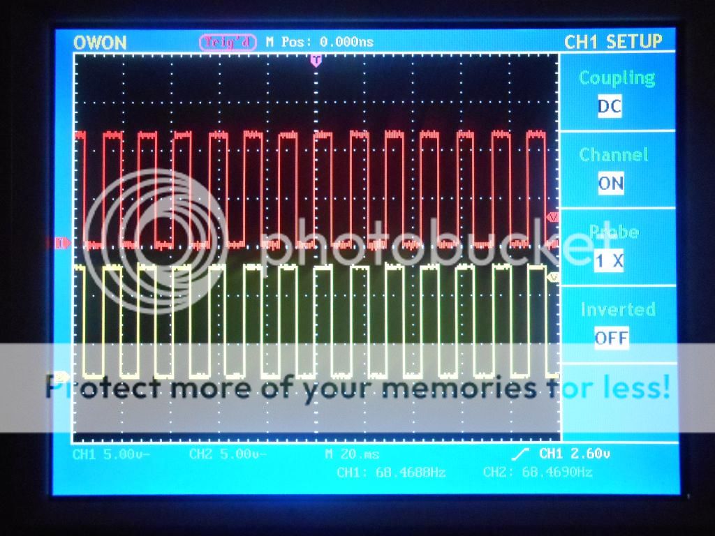
Does anyone know how to stop the two square waves from overlapping?, looking through some webpages it just seems to be a resistor between pins 5 & 7 to control the "dead time" for the mosfets. I'm using simplified version. For the resistor between pins 5 & 7 I'm using 100R but changing this value or even jumping the pins seem to have no effect, the two waveforms are a perfect overlapping match on my oscilloscope. Thank you.
http://i317.photobucket.com/albums/mm398/haz_1000/p89-f9_zpsc02dfc9d.gif
http://i317.photobucket.com/albums/mm398/haz_1000/p89-f9_zpsc02dfc9d.gif
Is this what you are looking for?
DSCN0152_zps36c77117.mp4 Video by haz_1000 | Photobucket
I've done a small video instead of a picture you might get a better idea.
DSCN0152_zps36c77117.mp4 Video by haz_1000 | Photobucket
I've done a small video instead of a picture you might get a better idea.
Thats great!! I was a little confused as the oscilloscope stacks the waveforms perfectly on top of each other when I use the auto set button, (trigger mode). But when the scope is in (auto mode) the video is the end result.
was not quite sure what a signal 180 degrees out of phase would look like on an
oscilloscope screen. thanks!!
was not quite sure what a signal 180 degrees out of phase would look like on an
oscilloscope screen. thanks!!
- Status
- This old topic is closed. If you want to reopen this topic, contact a moderator using the "Report Post" button.
- Home
- Amplifiers
- Power Supplies
- SG3525 problem