Wouldn't you want the heaters to be balanced around ground, rather than grounding one side, for hum rejection?
With a single balanced heater supply for all valves (ie. balanced with power humdinger to 0V), you could obtain a sense voltage for each valve that was just related to cathode-anode DC current. Insert a resistor in each heater lead of each valve (eg. 0.1 ohm). Then insert a trimpot across the heater terminals of each valve. With the wiper in centre position, the wiper voltage relative to 0V will have a DC bias, with AC signal nulled. A cathode-anode DC bias current of 0.1A would generate a 10mV DC sense signal - AC residual voltage could be filtered.
With a single balanced heater supply for all valves (ie. balanced with power humdinger to 0V), you could obtain a sense voltage for each valve that was just related to cathode-anode DC current. Insert a resistor in each heater lead of each valve (eg. 0.1 ohm). Then insert a trimpot across the heater terminals of each valve. With the wiper in centre position, the wiper voltage relative to 0V will have a DC bias, with AC signal nulled. A cathode-anode DC bias current of 0.1A would generate a 10mV DC sense signal - AC residual voltage could be filtered.
ClassZ,Hello, ...
I am using toroidal PP transformers so equalizing the current is important. To achieve that I would need some effective way of monitoring the current the drawn by each tube at the same time. That could be accomplished with 4 panel meters with a 0-200mA range.
Also, unfortunately all tube are powered off the same filament transformer (12.6 CT).
To measure the current I have thought of a couple of methods:
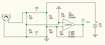
you should be able to get a signal proportional for the cathode current using a diffirential amplifier on an OPAMP as attached. All resistors shouls be precise, 0.1% should be enough.
The circuit allows to use the common 12V power supply for heating for all tubes. The common node input voltage for the OPAMP here is 6V which should be Ok for most circumstances.
Most important, the circuits returns the true signal about the cathode current and can be used in feedback nets. A good portion of the alternating cathode current goes through 12V power supply. You will not know about it unless you use current sence resistors in both cathode pins.
Attachments
Nice suggestion, but I doubt the bias control unit will be able to sense the individual currents as long as the four filaments are run from the same supply.
Besides, the OP said that he doesn't have the budget to get another transformer to isolate the filaments from each other. In that light, buying four filament supplies and a bias control unit is way out of his budget.
For a cheap solution to get the anode currents balanced I would do the following:
- put a current sense resistor or mA meter under the four DHTs to read the total current
- make sure there is some ripple on the 1,5kV supply (when you have a supply with a choke in the ground leg you could safely jumper this with a switch prior to switching the power on)
- balance the anode currents by minimizing the hum on the speaker outputs
(after that start saving for additional parts to isolate the filaments by getting them their own well filtered or regulated dc supplies which will facilitate individual current sensing, improve performance and -admit it- a monster amp like this deserves it)
Well, thank you all for your very kind and brilliant advice.
I truly appreciate it and thank you all.
In the end I made a decision to trade the large transformer for small 12.6v SMPS. The individual units would share no connection and thus allow for individual measurements to be taken reliably.
Irony is that for other GM100 amplifier I found myself having two distinct SMPS units as a single 17v transformer of adequate wattage was impossible to find. In the end this allowed me to mount current meters with no problems whatsoever.
In the long run the simplest - albeit maybe more costly - solution actually ends up costing less than the apparently convenient and cheap solution. As a matter of fact I honestly see no reason to get into this much trouble while building a DHT based amplifier. Just buy individual transformers and avoid the current sensing issue altogether!
To my defense I was reassured on using a single transformer for all tubes by my experience on a gu46 amp. At that time I was only concerned with cross-talk between channels and at the end of the construction phase found there wasn't any. I know the two issues are unrelated but it just goes to show that careful planning of everything (design and final construction) before hand is the only option.
thank you again for your help and suggestions. Maybe this thread will help others with the same problems.
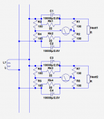
You can use your large transformer, and yet control and monitor the individual cathode currents: Rk1, .... ,n set the bias current and allow the monitoring via a simple bridge arrangement and a voltmeter.
Note that the resistors do not need to be particularly well matched, and the scheme works indifferently for any grounding arrangement of the heater winding
Note that the resistors do not need to be particularly well matched, and the scheme works indifferently for any grounding arrangement of the heater winding
Attachments
Last edited:
You could use a optocoupler with a resistor across the photodiode to sense the anode current. You can easily get 2500V isolation with an optocoupler, frequency responce should not be a problem and with rectified power line frequency.
Isolation is not the same as working voltage.
You can use your large transformer, and yet control and monitor the individual cathode currents: Rk1, .... ,n set the bias current and allow the monitoring via a simple bridge arrangement and a voltmeter.
Note that the resistors do not need to be particularly well matched, and the scheme works indifferently for any grounding arrangement of the heater winding
Looks very nice and I see where you are going (or at least I think I do
 ) but I am drawing 10.5A continuously. Isn't that a problem given your choice of resistors in the schematic?
You could use a optocoupler with a resistor across the photodiode to sense the anode current. You can easily get 2500V isolation with an optocoupler, frequency responce should not be a problem and with rectified power line frequency.
Got me there. How would you implement that?
Your cathode current is probably not 10.5A, unless you make a really big amplifier.Looks very nice and I see where you are going (or at least I think I do
If the 10.5A is the heater current, it will see the ~260mΩ reactance of the 10,000µF cap, which is still too much if a single tube draws that current, but is probably acceptable if it is shared by a number of tubes.
Anyway, you can increase the caps value almost indefinitely: modern, very low voltage E-caps are quite compact
An opto isolator amplifier such as HP's HCPL-7840 would be capable of providing an isolated sensed dc level from the anode circuit with good accuracy, as LED ageing is not part of performance. However, although it has a 5kV or 3750Vrms isolation rating, it has a 890V peak working voltage rating. The anode voltage is well above 890V when idle, let alone when the amp is amplifying. The same opto device working voltage level would by typical of other devices I suggest.
ClassZ, Elvee's scheme is what I suggested earlier - he proposes using a high value DC current sensing resistor of 22R, with an AC bypass so that there is negligible AC voltage dropped, given that you are powering the heaters from AC. The heater terminal humdinger may need to be a pot to get an AC null, depending on the response characteristic of the meter used.
ClassZ, Elvee's scheme is what I suggested earlier - he proposes using a high value DC current sensing resistor of 22R, with an AC bypass so that there is negligible AC voltage dropped, given that you are powering the heaters from AC. The heater terminal humdinger may need to be a pot to get an AC null, depending on the response characteristic of the meter used.
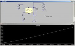
The Vout would not translate immediately to a measure of current.
Since Vout is proportional to current and ground referenced, you could make up a simple calibration chart and / or use an Arduino or other similar board to control a display or analog meter.
Each optocoupler is likely to be slightly different, and have some temperature effect on the calibration. The Vout will likely go up with increasing temp, even though the current remains constant.
Neither of these effects should be large enough to affect the amp's operation since tubes themselves are likely the largest variable. Even if you match the idle currents to a nanoamp, each tube will have a different Gm, so the current matching is valid only at one point.
Absolutely. I might just strap 4 cheap 5v voltmeters to the panel and print a small label with references. To be perfectly honest, I just want a measure of relative current draw between the two pairs of output tubes. If I know that 3.3v is more or less 200mA anode draw then I can simply make sure to remove difference between tubes of the pair.
- Status
- This old topic is closed. If you want to reopen this topic, contact a moderator using the "Report Post" button.
- Home
- Design & Build
- Equipment & Tools
- Sensing current in high voltage DHT circuits.