So now Im having trouble figuring out if and where the negative feedback resistor is.
The feedback resistor is 82k, so look for the Grey-Red-Orange bands.
> The resistor/cap im pointing at in the picture dont seem to be in the schematic....
The cap is wrong. It may be a bogus mod. If it is less than 0.02ufd it *may* be a factory tweak to brighten-up the amp (though this is a dubious way to do it).
I do not see two 1.8K in that picture. Are you good with color codes? It is a very useful skill. If you have color blindness, have someone help.
Attachments
Last edited:
Wow awesome labeling on the photo! Thanks!
I just looked up the code for the resistor - the one you labeled as 82k to OT - it should be 92k but it reads at ~1900ohms. (I havent been reading the resistor codes - just measuring them on my meter)
Gonna pull that cap and replace the negative feedback resistor!
EDIT;
Why would anyone put a cap in that location?
Also, wow - just replaced the negative feedback resistor and it is still reading as ~1900ohms... hows that work? it was 220k (chose a higher value) before installed - now it reads at 1900?
Last edited:
You often can't measure resistors 'in situ'. If there are other paths in parallel with the resistor, you would need to disconnect one end of the resistor to make the measurement.
In this case, one end of the 82k is grounded through the output transformer secondary and the other end is grounded via the 1.8k resistor. So what you are measuring is the 82k resistor in parallel with the 1.8k (plus a little bit of series resistance in the output transformer secondary).
In this case, one end of the 82k is grounded through the output transformer secondary and the other end is grounded via the 1.8k resistor. So what you are measuring is the 82k resistor in parallel with the 1.8k (plus a little bit of series resistance in the output transformer secondary).
Last edited:
Looks like you have the power switch controlling the neutral (white) from the wall. Although this is functional and was common in the past, it is not kosher. The path all the way to the power tranny is still "hot," all the time. Black>fuse>switch>tranny-side-A & white>tranny side B is the safest.
Gonna address the power switch routing soon.
Not having much luck with trying the post-phase master volume. I got a 1meg (log) pot and it has a strange taper. Seems like it only has all the way down, one notch up, and then max. The curve on it is very strange - not smooth at all. Doesnt sound good in any position either.
Not sure if the gain staging in this amp is particularly conducive to a master vol.. Kinda wish the first vol pot and tone stack were in between the first 2 triodes instead of the 2nd.
Don't know if Im gonna mess with that though. Maybe just start putting together a new circuit for a scratch build.
Hopefully gonna start work on a nice little cabinet for this guy tonight tho!
Also - removed one of the input jacks to make space for master vol. Previously there was a wire running from each "sleeve" of the jacks to pins 2 and 7 (grids) on the first 12ax7. I took the wire from the removed jack and attached it with the other one. Now pins 2/7 are both being fed from the "sleeve" of one jack. I assume this is correct?
EDIT;
OH I also just clipped out the negative feedback resistor just to see how that sounded - need to take the amp someplace I can really crank it to see...
>> 68k resistor across the hot/gnd of the primary side of the power transformer? There is also a symbol Im not familiar with - little circle with 2 lightning bolts?
> Neon indicator lamp?
Yes.
I have never seen *that* symbol for a neon. More traditional is this symbol:

But in context, it can't be much else.
You could also poke around the 117V entrance wiring (un-plugged!) and match what you find to the schematic.
> Neon indicator lamp?
Yes.
I have never seen *that* symbol for a neon. More traditional is this symbol:
But in context, it can't be much else.
You could also poke around the 117V entrance wiring (un-plugged!) and match what you find to the schematic.
Time for what might be a last update.
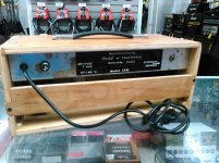
Made a quick and dirty box to house this little guy!
I may try and get a master volume in to this amp - or I may just leave it as it is and start a new project.
I attempted to pop in a post phase MV a-la Rob Rob Robinette's "trainwreck type-3"
Amp Mods
But it really didnt seem to work at all. The taper seemed funky, went from basically off to full volume without much in between - was a bit scratchy - and just sounded bad. I wondered if maybe it was just because I only had it alligator clipped in for testing - maybe if it was soldered properly it would work better?
Anyone know why this type of MV may not be working well for this amp?
(here's the schematic I have for the amp)
http://bartell.vintageusaguitars.com/files/8412/8292/1460/ContCA15.pdf
Attachments
- Status
- This old topic is closed. If you want to reopen this topic, contact a moderator using the "Report Post" button.
- Home
- Live Sound
- Instruments and Amps
- Semi-Noob trying to make sense of my first project