I just went through some spice simulations and what I am seeing I can't believe my eyes !!!
By using active filtering before the amp greatly reduces the resistor power and voltage requirements.
Much much more so than I had expected than by just using resistances alone for the panel equalization.
I will get the data pictures together and post them later as I have a few different situations to show.
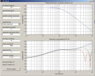
I didn't realize that a 6db per octave slope was 20db per decade !!!
When designing for a 2 decade 200Hz to 20Khz range there is a 40db difference in voltages in order to have a flat response.
No wonder my amp and ears were straining !!!!
A 6 db slope may not look like much on graph but it is a lot ratio wise once you get through all of the octaves.
More on this later !!
Cheers!!!
jer")
By using active filtering before the amp greatly reduces the resistor power and voltage requirements.
Much much more so than I had expected than by just using resistances alone for the panel equalization.
I will get the data pictures together and post them later as I have a few different situations to show.
I didn't realize that a 6db per octave slope was 20db per decade !!!
When designing for a 2 decade 200Hz to 20Khz range there is a 40db difference in voltages in order to have a flat response.
No wonder my amp and ears were straining !!!!
A 6 db slope may not look like much on graph but it is a lot ratio wise once you get through all of the octaves.
More on this later !!
Cheers!!!
jer
maybe this has being asked before but why does the wire count and width of the panel not corespond with the amount of wires you say each sigment has
its says 10 10 10 sigments then it sayed total wires 50, according to me its 30. he then uses the 50 with the heart to heart wire distance to say something about the total width of the panel. wich is not correct. i wonder if the rest of the graphics is correct this way. i mean if he takes that fault into the calculation you get some weird results.
but besides that awesome
Because the First 10 is assumed as the center section and the next successive 10's are account for the sections on each side of the center section.
Another words as follows,
end middle center middle end
10 -- 10 ---- 10 ---- 10 -- 10
For a total of 50 wires.
Heart to heart means the center to center distance of the wires and it calculates the active area of the diaphragm.
I don't know how much is accounted for for the frame.
For a large panel this difference has little effect but for a smaller width panel it can be as much as a +3db of difference according to some of the other simulators on the low end response.
Changing the low end dipole drop off slightly.
Kind of like adding baffles or wings in which has a positive effect on the low end extension.
jer
Last edited:
maybe this has being asked before but why does the wire count and width of the panel not corespond with the amount of wires you say each sigment has
The schematic for a 10 segment ESL design geraldfry was analyzing may help clarify what the wire count and resistor values actually represent.
http://www.diyaudio.com/forums/plan...r-esl-simulator-esl_seg_ui-3.html#post2942303
verry ncie to play with, but as calvin mentioned the 6DB rollof is easy done by a resistor in front of the tranny wich also helps the amplifier in the high frequency as well. to use both i need to play allot
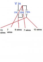
in the picture i modeled my new panel im working on, i have 6 wires in the middle without any ressistors then 7 to the sides wich are tamed with 900Kohm
the hump from 9000 i would like to tame with a resistor before the tranny. im not sure yet how this is gone work out.
also im not sure if the 900K ohm has to be power resistors ??? can it be ell cheapo 0.25 watt or something.
on last question does it mean 900K on each stator? at least thats what i thought
Attachments
Yes, it is a very cool program.
The first set the resistors take the bulk of the power as determined by the highest frequency's.
The spice sim's that I show are for test tones at a full power and the resistors need be fairly large.
But, In the real world this is not the case for the most part as the highest frequency's occur as intermittent peaks and not a constant level.
In one of these threads I show more realistic values of the needed power ratings.
I will try to find that post for you.
Much like your simulation I was going to keep the high frequency rise and omit the first resistor as it needs to be the highest power rating than the rest of them and use a pre-filter before the amplifier to adjust for this compensation.
This does two things,
#1 it lowers the overall needed power rating for all of the rest of the resistors.
#2 it lessen's the demand even more on the power amplifier, as does compensation does for a non-segmented panel.
The whole Idea for the segmentation is to even out the overall horizontal dispersion and the first resistor is really just a power waster and can be replaced by active filtering.
I think a simple High frequency shelving EQ would do it......IE the treble tone control found on most all systems.
jer
Well filtering before amp would solve rise in freq. but that's not the reason I do this, ofc
The sigment without resistor is so small it helps the dispersion to be only 1 dB down on 15 degree angle at 19 k. Still there's a small rise in freq response which I try to get rid of with a series resistor in the primarie of the trannie, which makes it an easier load on the amp. As wel as on the trannie. The rise I can fix like that easy with to benefits , the dispersion I can only fix after the trannie or to use separate trannies. But how much watt where your resistors in the segmentation ?
The sigment without resistor is so small it helps the dispersion to be only 1 dB down on 15 degree angle at 19 k. Still there's a small rise in freq response which I try to get rid of with a series resistor in the primarie of the trannie, which makes it an easier load on the amp. As wel as on the trannie. The rise I can fix like that easy with to benefits , the dispersion I can only fix after the trannie or to use separate trannies. But how much watt where your resistors in the segmentation ?
on last question does it mean 900K on each stator? at least thats what i thought
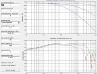
See Configuration (1) for the meaning of the 900K resistors. It is one to each of the 7 wire groups on one stator. The other stator has no resistors.
Alternatively, you can use the more common symmetric arrangement shown in Configuration (2).
also im not sure if the 900K ohm has to be power resistors ??? can it be ell cheapo 0.25 watt or something.
The required power rating depends on what voltage you are driving the stators with. Also, you need to consider the voltage handling capability of the resistors, not just power handling. With D/S = 1mm, maximum recommended stator voltage would be about 3kVrms. From this I would estimate that worst case voltage across the 900K resistors in Configuration (1) would be 2500Vrms @ 6Khz when a 1ohm resistor is put in series with the primary. Power dissipated in the 900K resistor would be about 7 Watts. Of course this is worst case with test tones, music will require much less power capability than this.
You could probably get away with using a single 1W - 2W resistor.
However, most resistors have voltage ratings in the 500V to 700V range.
So for reliability, I would use two or three 1W resistors in series for each of the 450K resistors in Configuration (2)
I agree. The series resistor in the primary of the transformer is highly recommended as it protects the amplifier from core saturation at low frequencies and makes the load easier(higher magniture, more resistive phase) at high frequencies.Still there's a small rise in freq response which I try to get rid of with a series resistor in the primarie of the trannie, which makes it an easier load on the amp. As wel as on the trannie.
.
Attachments
Last edited:
See Configuration (1) for the meaning of the 900K resistors. It is one to each of the 7 wire groups on one stator. The other stator has no resistors.
Alternatively, you can use the more common symmetric arrangement shown in Configuration (2).
The required power rating depends on what voltage you are driving the stators with. Also, you need to consider the voltage handling capability of the resistors, not just power handling. With D/S = 1mm, maximum recommended stator voltage would be about 3kVrms. From this I would estimate that worst case voltage across the 900K resistors in Configuration (1) would be 2500Vrms @ 6Khz when a 1ohm resistor is put in series with the primary. Power dissipated in the 900K resistor would be about 7 Watts. Of course this is worst case with test tones, music will require much less power capability than this.
You could probably get away with using a single 1W - 2W resistor.
However, most resistors have voltage ratings in the 500V to 700V range.
So for reliability, I would use two or three 1W resistors in series for each of the 450K resistors in Configuration (2)
I agree. The series resistor in the primary of the transformer is highly recommended as it protects the amplifier from core saturation at low frequencies and makes the load easier(higher magniture, more resistive phase) at high frequencies.
.
Thanks allot that rx
See Configuration (1) for the meaning of the 900K resistors. It is one to each of the 7 wire groups on one stator. The other stator has no resistors.
Alternatively, you can use the more common symmetric arrangement shown in Configuration (2).
The required power rating depends on what voltage you are driving the stators with. Also, you need to consider the voltage handling capability of the resistors, not just power handling. With D/S = 1mm, maximum recommended stator voltage would be about 3kVrms. From this I would estimate that worst case voltage across the 900K resistors in Configuration (1) would be 2500Vrms @ 6Khz when a 1ohm resistor is put in series with the primary. Power dissipated in the 900K resistor would be about 7 Watts. Of course this is worst case with test tones, music will require much less power capability than this.
You could probably get away with using a single 1W - 2W resistor.
However, most resistors have voltage ratings in the 500V to 700V range.
So for reliability, I would use two or three 1W resistors in series for each of the 450K resistors in Configuration (2)
I agree. The series resistor in the primary of the transformer is highly recommended as it protects the amplifier from core saturation at low frequencies and makes the load easier(higher magniture, more resistive phase) at high frequencies.
.
Thanks allot that explains allot, and confirms allot which is also nice caus I'm trying to understand things. When I finish the stators I will give this configuration a try !!! Thanks
Isn't config 1 out of balance ? Front filtered and back stator not ?
Although the physical appearance may look unbalanced, what matters is the voltage response across the ESL segment capacitance. Configuration 1 & 2 provide the same voltage response as it is an RC series network. It doesn't matter if you put all the resistance on one side or the other, or some on each side. All that matters is the sum of the resistances in series with the segment. I have confirmed this with measurements.
Thanks for your confirmation on the "Configuration 1",Bolserst.
I was wondering about that.
This will help greatly to reduce the complexity and mostly the cost of my little panel design.
I have yet to get the resistors and is one of the reasons why I have not finished them up yet as mounting the diaphragm is all that is left to do and they are ready to run.
Cheers!!
jer
Hi guys,
Sorry to interrupt this thread, but as I am well underway with building my own hybrid electrostat I'm confused to wether my design assumptions are right. I have made the following electrical circuit for each stator (front and back). How does this compare with the design I made in ESL_SEG_UI? Can you tell me ? Thanks already,
Jeroen
Attachments
I used 7 to 10 watt resistors on my segments, but with 1/3 or 1/4 of the total value in connected in series to achieve the desired value.
Wiring in series also allows you to get closer to the design value uy juggling the values of the individual resistors a bit. You must NOT use wire wounds- I had some real problems with response, and am assuming it was due to the inductance.
HV metal films are not easy to find, nor are they inexpensive new (think: surplus) but I think they made a difference in my project.
I have made the following electrical circuit for each stator (front and back). How does this compare with the design I made in ESL_SEG_UI?
Hello jeronimo83,
Based on your ESL_SEG_UI inputs, the attached schematics show resistor values and wiring connections that would give the calculated response.
If I understand your electrical circuit description correctly, you should use the resistor values in Configuration (4).
Configuration (1) is most directly comparable with the inputs from the program.
Configuration (2) is the symmetric version of (1) where half of the resistance is placed on each stator segment.
Configuration (3) left and right side portion of each segement are connected and driven with one resistor ladder.
Configuration (4) is the symmetric version of (3)
As mentioned previously in this thread, often the resistor for segment 1 is moved to the primary side of the transformer where it can provide core saturation protection as well. In your case with a 150:1 step-up ratio, the 25K resistor could be replaced with a 1 ohm resistor on the primary side of the transformer(resistor "R" in the schematics).
Attachments
You must NOT use wire wounds- I had some real problems with response, and am assuming it was due to the inductance.
I don't doubt the problems you had, but inductance would have to be 100mH or more to start affecting the response.
Do you happen to recall what resistor values and manufacturer part number you were using?
I'm wondering if perhaps the strange behavior resulted from operating well outside their voltage rating.
- Status
- This old topic is closed. If you want to reopen this topic, contact a moderator using the "Report Post" button.
- Home
- Loudspeakers
- Planars & Exotics
- Segmented Wire Stator ESL simulator (esl_seg_ui)