Hi all,
I'm building a 3 channel Leach amp- all is up and working great, but I'm adding a small subcircuit that needs +/-12V (low current draw, just 2 op amps and a 5mm LED: maybe 30mA). I plan to use some "leftover" secondaries, rectify, then use lm7812/7912's to regulate the supply down to 12V.
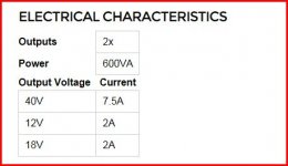
I'm using an Antek 6440 power transformer which includes 2x 40V (tied up for the amps), an 18V and a 12V secondary. I understand wiring the 2 lower voltage secondaries in series, but I'm not sure what to do with the two leads that are tied together, the new "center tap." Should this tied to ground or just isolated?
If ground, just run it to chassis ground or have it serve as the ground only for the subcircuit it's powering?
Thanks for any help!
I'm building a 3 channel Leach amp- all is up and working great, but I'm adding a small subcircuit that needs +/-12V (low current draw, just 2 op amps and a 5mm LED: maybe 30mA). I plan to use some "leftover" secondaries, rectify, then use lm7812/7912's to regulate the supply down to 12V.
I'm using an Antek 6440 power transformer which includes 2x 40V (tied up for the amps), an 18V and a 12V secondary. I understand wiring the 2 lower voltage secondaries in series, but I'm not sure what to do with the two leads that are tied together, the new "center tap." Should this tied to ground or just isolated?
If ground, just run it to chassis ground or have it serve as the ground only for the subcircuit it's powering?
Thanks for any help!
Whatever you no need- just leave it. Dont use it at all. Isolate it.
Logic is simple. If one wind gives you 5 AC, second is 5 AC, all together ( connected in serial) it is about 10 AC ( all voltages are examples). The middle point can be used as virtual GRAUND if you need + 5 DC ( or whatever you have after rectifier) and -5 DC. If you need only single +10 DC, dont use virtual GRAUND at all.
P.S make sure you understand what is true GRAUND before you connect it to your chassis =)
Last edited:
... an 18V and a 12V secondary. I understand wiring the 2 lower voltage secondaries in series ...

well, a quick search reveals that the low voltages are single secondaries
so what are you planning here ?
wire the 18V and 12V in series for +/-12V regs, and creating a pseudo midpoint/ground with resistors ?
Attachments
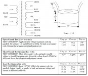
The Antek website is poor... I looked to see just what the windings are. No diagrams that I could see, just a description that reads at face value, two off, 40 volt, 18 volt and 12 volt windings. So there should be twelve separate secondary leads...... but are there ?
Attachments
well, a quick search reveals that the low voltages are single secondaries
so what are you planning here ?
wire the 18V and 12V in series for +/-12V regs, and creating a pseudo midpoint/ground with resistors ?
You are doing well to find that tinitus
I agree... wire in series.
The fact that they are unbalanced doesn't matter. So you end up with say -17 volts and + 25 volts. No problem, just feed the 7812 regs as normal and connect the midpoint of the windings to main ground.
The fact that they are unbalanced doesn't matter. So you end up with say -17 volts and + 25 volts. No problem, just feed the 7812 regs as normal and connect the midpoint of the windings to main ground.
I suppose you could do that too
would 25V be ok for a 12V reg ?
or will it depend on receiver curcuit current draw ?
I suppose you could do that too
25V input is not a bit much for a 12V reg ?
Nah
It should be OK, 35 volts is the max input for a 78/79 reg.That way, a ground will be created
like this ?
Attachments

Thanks for the responses all. A little more info:
This subcircuit will be an input buffer and a summing circuit to combine the low freq from the L/R channels so my third channel can amp a subwoofer. There will also be a 5mm power indicator LED.
So I need a clean/stable +/-12v to run my op amps (buffers and summing).
I know I can use a single ended supply, but didn't want to have to redraw my circuit design to bias the op amps. Instead, my thinking was I can use these 12v/18v secondaries since they otherwise would just be sitting there unused.
With my original idea or combining secondaries in series, I would get 12+18v=30Vac --> 42.4Vdc --> +/-21.2Vdc after bridge rectifier. Since my circuit is only drawing ~30mA, the voltage regulators can easily handle this ~20V and I probably wouldn't even need a heatsink. My only question was what to do with the 2 inner leads - isolate or ground (as in star ground of chassis which goes to safety ground)? Does the circuit ground have to be referenced to the transformer or can I just isolate those leads and run a separate wire so the circuit can reference to 0V?
I've just read up a little on the voltage doubler, but won't this be a single ended supply? I'd rather not have to make a circuit to drive a virtual ground.
Thanks again everyone.
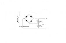
I would just wire it as a normal -/+ supply as I outlined earlier with the windings in series. One bridge rectifier and two reservoir caps. One cap will see around 25 volts ad the other around 16 volts. Thats no problem, 16 volts is enough overhead for a 78/7912.
The centre OV rail of the new supply (which is the junction of the two windings) connects to your main 0V line.
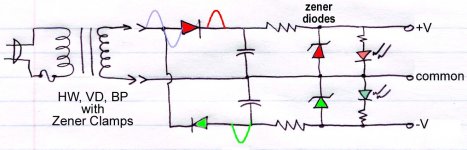
Another option... and it maybe better as the current requirement is so low... is to use a simple zener shunt regulator off the main rails. Two resistors and two zeners, it gives better performance than a 78/7912, and no multiple grounds to deal with.
The centre OV rail of the new supply (which is the junction of the two windings) connects to your main 0V line.
Another option... and it maybe better as the current requirement is so low... is to use a simple zener shunt regulator off the main rails. Two resistors and two zeners, it gives better performance than a 78/7912, and no multiple grounds to deal with.
Another option... and it maybe better as the current requirement is so low... is to use a simple zener shunt regulator off the main rails. Two resistors and two zeners, it gives better performance than a 78/7912, and no multiple grounds to deal with.
like this ?
Attachments
like this ?
Sort of
I was thinking direct of the main DC rails, but yes, either or
This subcircuit will be an input buffer and a summing circuit to combine the low freq from the L/R channels so my third channel can amp a subwoofer. There will also be a 5mm power indicator LED.
I assume the inputs to this circuit are piggybacked off the main unit inputs?
With my original idea or combining secondaries in series, I would get 12+18v=30Vac --> 42.4Vdc --> +/-21.2Vdc after bridge rectifier.
That is not correct. The windings are 12-0-18 so your supply will end up +-16V DC approx with some extra voltage being burned off on the higher rail by the regulator.
Since my circuit is only drawing ~30mA, the voltage regulators can easily handle this ~20V and I probably wouldn't even need a heatsink.
18V winding results in 25V DC rail. 25-12=13 volts so power dissipation is approx 0.4 watts. This should be OK for a TO-220 without heatsink, but it will certainly be pretty hot to the touch.
My only question was what to do with the 2 inner leads - isolate or ground (as in star ground of chassis which goes to safety ground)? Does the circuit ground have to be referenced to the transformer or can I just isolate those leads and run a separate wire so the circuit can reference to 0V?
If my assumption of piggybacking above is correct, I would not connect the ground to main ground because it could create a ground loop. By piggybacking the signal leads it will tie the ground to the right potential.
I've just read up a little on the voltage doubler, but won't this be a single ended supply? I'd rather not have to make a circuit to drive a virtual ground.
They can be, but, see my schematic I mentioned - it's a split supply.
I assume the inputs to this circuit are piggybacked off the main unit inputs?
Yes, each input jack will see one op amp buffer that leads to my new circuit and the amp circuits in parallel.
Yes, you're right. But since the secondaries aren't symmetric, it seems the 0 in 12-0-18 won't actually be at 0V... Am I wrong on this? Also, so you're saying just take the actual signal lead to the op amp, don't even worry about bring the input jacks sleeve/ground?That is not correct. The windings are 12-0-18 so your supply will end up +-16V DC approx with some extra voltage being burned off on the higher rail by the regulator.
18V winding results in 25V DC rail. 25-12=13 volts so power dissipation is approx 0.4 watts. This should be OK for a TO-220 without heatsink, but it will certainly be pretty hot to the touch.
If my assumption of piggybacking above is correct, I would not connect the ground to main ground because it could create a ground loop. By piggybacking the signal leads it will tie the ground to the right potential.
I went ahead and wired it in series and took some AC measurements. This is with no load and results are:
Brown: 18V secondary
Orange: secondary
Brown to Orange = 31.8Vac
Center (brown and orange tied together) to Brown = 19V
Center (brown and orange tied together) to Orange = 12.9V
Ground (Chassis) to center = 17Vac
Ground to brown = 34.5V
Ground to orange = 5.4V
So, as expected, the inside connection is not at 0V since it's not symmetric. Therefore, just leave it isolated and reference the subcircuit (past the input stage) to my chassis ground?
My head's starting to spin
- thanks for the help though, I'm not as experience on the power side of things so this is helping my understanding a great deal.- Status
- This old topic is closed. If you want to reopen this topic, contact a moderator using the "Report Post" button.
- Home
- Amplifiers
- Power Supplies
- Secondary wiring w/ 2 different windings