the clarity had nothing to do with jpeg quality though.. it was simply at too low a resolution. If it had not been single colour the software may have dithered it.
PNG is good if you can use it, a 256-colour grayscale image compresses well with that.
Personally im happy to scroll a large, clear schematic
PNG is good if you can use it, a 256-colour grayscale image compresses well with that.
Personally im happy to scroll a large, clear schematic
Attachments
Last edited:
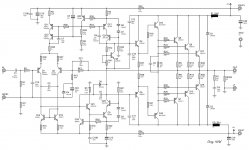
The MPSA42 has nicer stats,
But in honesty either works well.
This circuit is a evolution and changes constantly, used for me to learn more.
I don't have instruments to measure THD/distortion,
So to answer your question, the choice to replace the 2n5551 was purely based on datasheets.
I can't notice any difference, on scope and on listening, they the same to me.
What I have not done yet, is check by how much i can lower CDOM,
But I think this will be the last time I use Miller compensation.
Keeping Q23/24 MJE340/350 is also the same
Regards
Last edited:
Why are R41 & R42 different value?
They don't need to be different values, they were originally the same value then I increased R42 for already mentioned reason, but there was no 'need' to increase R41, and I was happy with stability at current value, so I didnt change R41 to same value as R42,
This is not symmetric VAS circuit so I don't mind them not being same value.
I've not had any chance to work on the amplifier, and sadly wont till January.
@AndrewT, sorry for not answering sooner, for some reason I didn't see the question on the resistors, guess I was just focusing on trying to export jpg in a better way.
Regards
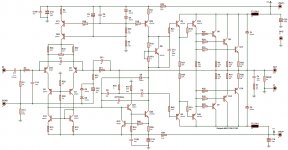
Ok after getting the previous circuit working, but not confident on the cascode of enhanced Vas and Vas current source I've decided to change it again.
I'm hoping after this revision that it will be my final, and finally will see a permanent enclosure and a place in my sitting room.
I'm awaiting components from store to arrive in next week or so.
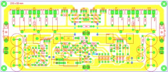
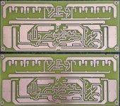
Here is the PCB's etched with toner transfer.
Have not drilled the pcb yet
The PCB is hopefully final version but allows me to tweak it still.
I'll be trying TMC but left space to revert to miller cap if needed.
With TMC phase margin is 58deg.
Q1,2,13,14,11,22 2N5401/2N5551 can be substituted with rotated BC550/BC560.
Regards
I'm hoping after this revision that it will be my final, and finally will see a permanent enclosure and a place in my sitting room.
I'm awaiting components from store to arrive in next week or so.
Here is the PCB's etched with toner transfer.
Have not drilled the pcb yet
The PCB is hopefully final version but allows me to tweak it still.
I'll be trying TMC but left space to revert to miller cap if needed.
With TMC phase margin is 58deg.
Q1,2,13,14,11,22 2N5401/2N5551 can be substituted with rotated BC550/BC560.
Regards
Attachments
Last edited:
You've done well with the toner transfer, which paper were you using ?
I use Press 'n Peel Blue about $1 a sheet here.
An externally hosted image should be here but it was not working when we last tested it.
Regards
I would like some help on deciding what feedback capacitor to use.
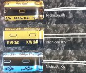
I have these 3 capacitors in my component box, all same diameter to fit pcb.
The PCB does not allow for greater diameter caps.
1.) http://www.nichicon.co.jp/english/products/pdfs/e-kw.pdf
Nichicon KW 1000uF 25V
2.) http://www.nichicon.co.jp/english/products/pdfs/ka_web_e.pdf
Nichicon KA 1000uF 25V
3.) http://products.nichicon.co.jp/en/pdf/XJA043/e-fg.pdf
Nichicon FG 1000uf 6.3V
The Nichicon FG is only 6.3V rated, physically same size as two caps above it.
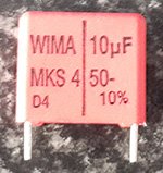
Also need advice with input capacitor please.
Two choices.
This capacitor I already have in my component box.
a.) MKS4-10/50/10P15 WIMA | Mouser
10uF 50V
I'll have to purchase this capacitor, but it should fit. But this cap is 4.7uF, which is less than 10uF of capacitor above.
b.) Buy Polypropylene Film Capacitors Radial polyprop cap,4.7uF 250V 20.6mm Panasonic ECWF2475JA online from RS for next day delivery.
4.7uF 250V
Thanks
I have these 3 capacitors in my component box, all same diameter to fit pcb.
The PCB does not allow for greater diameter caps.
1.) http://www.nichicon.co.jp/english/products/pdfs/e-kw.pdf
Nichicon KW 1000uF 25V
2.) http://www.nichicon.co.jp/english/products/pdfs/ka_web_e.pdf
Nichicon KA 1000uF 25V
3.) http://products.nichicon.co.jp/en/pdf/XJA043/e-fg.pdf
Nichicon FG 1000uf 6.3V
The Nichicon FG is only 6.3V rated, physically same size as two caps above it.
Also need advice with input capacitor please.
Two choices.
This capacitor I already have in my component box.
a.) MKS4-10/50/10P15 WIMA | Mouser
10uF 50V
I'll have to purchase this capacitor, but it should fit. But this cap is 4.7uF, which is less than 10uF of capacitor above.
b.) Buy Polypropylene Film Capacitors Radial polyprop cap,4.7uF 250V 20.6mm Panasonic ECWF2475JA online from RS for next day delivery.
4.7uF 250V
Thanks
Attachments
The feedback cap value depends on the adjacent resistor value and the LF passband you require.
1000uF (1mF) seems unusually large.
The input capacitor (DC blocker) value depends on the Zin of the power amplifier and the required LF pass band. 10uF and 4u7F seem unusually large.
1000uF (1mF) seems unusually large.
The input capacitor (DC blocker) value depends on the Zin of the power amplifier and the required LF pass band. 10uF and 4u7F seem unusually large.
Circuit is in post 89,
The feedback cap is oversized, as I read that this can be advantages.
Yes this is correct, oversized cap, lower voltage at low frequecies on it and lower distortion(read D. Self).
Do you realise that Cherry's LF phase correction will allow you to increase R1 to 66k and thus allow 1u5 as the input cap?
You would add a 44k//xxuF in series with RF1//CF1
xx is described in his papers. Two have been posted on the Forum.
I use RF1=33k3 and 66k6//4u7F with R1=100k and that needs just 1uF as the DC blocker.
It works very well for me.
You would add a 44k//xxuF in series with RF1//CF1
xx is described in his papers. Two have been posted on the Forum.
I use RF1=33k3 and 66k6//4u7F with R1=100k and that needs just 1uF as the DC blocker.
It works very well for me.
Last edited:
No I don't know about Cherry's LF phase correction, it's something I'll make time to look into.
Thanks.
As for input cap @ 10uf, I have the caps on hand, that's why I asked about using them, not because I thought that the input cap needed to be that big,
On my previous amp I used a 4.7uf, but I don't have any on hand, I might have 2.2uf, I'll have to check.
Thanks.
As for input cap @ 10uf, I have the caps on hand, that's why I asked about using them, not because I thought that the input cap needed to be that big,
On my previous amp I used a 4.7uf, but I don't have any on hand, I might have 2.2uf, I'll have to check.
Last edited:
This amp build will take some time as I won't be able to work much on it this month.
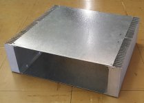
Here is the enclosure in the making, the heatsinks must still get final finishing off, and the screws are not counter sunk yet.
These heatsinks are cheap here 200mm long x 40 x 130 which is to short for what I wanted, so I had to bolt 2 of them together per side
But now that the heatsinks are drilled, Ill give them some work then attach amps and do the initial power up checks and settings.
It will be a single supply with a single bridge with 30000uF per rail feeding both channels from a 45Vac-0-45Vac 500VA toroidal.
The toroidal was chosen from what I already have, so to the 6x10000uF 100V caps.
Regards
Attachments
- Status
- This old topic is closed. If you want to reopen this topic, contact a moderator using the "Report Post" button.
- Home
- Amplifiers
- Solid State
- Second attempt at Building my own amp from scratch