I have opened a new webpage about DAC chips test.
The test will be with 2 different output stage: hybrid vacuum tube or simple transformers.
Each DAC chip will be tested in the best condition depending to the characteristics.
- some will have a passive I/V and other an active I/V
- when possible will be used a modo configuration
Here the link with the first webpage:
http://www.audiodesignguide.com/DAC_final/DacFinal.html
Any contributtion is welcome!
2x15 ohm is for LP-filtering I guess, but 2x220? Are you using proper decoupling before/after regulator, like 0.1µ polypropylene?
Really interesting test by the way, are you intending to test the OP275 with other popular audio OPs like OPA134 etc? Is -80dB the limit of your equipment?
Keep it up
edit: typo
Really interesting test by the way, are you intending to test the OP275 with other popular audio OPs like OPA134 etc? Is -80dB the limit of your equipment?
Keep it up
edit: typo
Well the shunt seems ok I guess, I've never used it myself. Though I don't quite follow why you've settled with 100ohm (2x200 for load relaxation) after reading the white paper...
I'm myself building a DAC with ad1896, pcm1798 and opa2134 as IV. I'll benchmark that one with my NAD 521BEE (older DAC, NE5534) and it would be really interesting if we conclude something similar
I'm using cheap 2x3000µF for the supply with 7812s for the OPs and lm1117 for all lower voltages. After each regulator I make shure to use low impedance caps, hoping that would keep enoguh decpoupling in pair with 0.1µ polyprop and 0.1µ ceramic IC-bypass.
Keep it up!
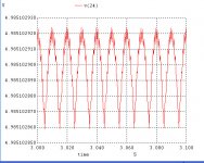
shunt ripple
I have simulated the shunt with:
vp 20 21 dc 0 ac 15 sin(0 15 50)
d1 0 20 D1N5406
d2 0 21 D1N5406
d3 20 19 D1N5406
d4 21 19 D1N5406
c1 19 0 4700uF
c2 19 0 4700uF
r0 19 22 7.5
c3 22 0 4700uF
c4 22 0 4700uF
r1 22 24 110
r3 24 23 1500
r4 23 0 1500
c5 24 0 22uf
x1 23 0 24 TL431
rl 24 0 100
I have simulated the shunt with:
vp 20 21 dc 0 ac 15 sin(0 15 50)
d1 0 20 D1N5406
d2 0 21 D1N5406
d3 20 19 D1N5406
d4 21 19 D1N5406
c1 19 0 4700uF
c2 19 0 4700uF
r0 19 22 7.5
c3 22 0 4700uF
c4 22 0 4700uF
r1 22 24 110
r3 24 23 1500
r4 23 0 1500
c5 24 0 22uf
x1 23 0 24 TL431
rl 24 0 100
Attachments

TL431 model
I use Winspice3 and this TL431 model:
* REFERENCE
* | ANODE
* | | CATHODE
* | | |
.SUBCKT TL431 1 2 3
V1 6 7 DC 1.4V
I1 2 4 1E-3
R1 1 2 1.2E6
R2 4 2 RMOD 2.495E3
R3 5 7 .2
D1 3 6 DMOD1
D2 2 3 DMOD1
D3 2 7 DMOD2
E1 5 2 POLY(2) (4,2) (1,2) 0 710 -710
.MODEL RMOD RES (TC1=1.4E-5 TC2=-1E-6)
.MODEL DMOD1 D (RS=.3)
.MODEL DMOD2 D (RS=1E-6)
.ENDS
- Status
- This old topic is closed. If you want to reopen this topic, contact a moderator using the "Report Post" button.
- Home
- Source & Line
- Digital Source
- Searching the better DAC testing all