Everything you try or you think or you design in ampifier circuit topology has been tried - designed before , one day I was looking in the book of Mr. Slone and then came to me the idea of this power follower and the best way to drive it with DC coupling is an SRPP ( and here is the " prototype " the DC coupling and the IGBTs ) , so if your point is from where I got this idea ? the above is my answer , that's why the similarities doesn't surrprise me , because similar way of thinking leads to similar solutions .
Class A power follower has been used like output stages in Power amps too and not only as headphone amps .
Class A power follower has been used like output stages in Power amps too and not only as headphone amps .
Last edited:
I hope you are as successful in your design implementation as I was with mine. A very proven design concept! Main design consideration is choise of Mosfets, I'm trying K2700 N-Mosfets in my latest amp design as gate drivers to prevent blocking cross over distortion caused from the charge change in the coupling cap when the gate starts to conduct...
Keep us posted on your progress, and your final schematic....
Keep us posted on your progress, and your final schematic....
people use hexfets in audio ,sure, but i do not like idea of xA ..xyA quescient currentWhat is optimal for audio or not is a big story , that we can't cover it here ( it's a big debate ) , in my opinion most devices can play good if we treat them right , as for those IGBTs , their switching characteristics is very good they are new generation IGBTs , but here we have class A amp therefore we don't have to worry about those characteristics, it will matter if we have class AB amp .
..or idea of having huge heatsinks
aargh, that designs where only one transistor does all the useful workLooks more like a headphone hybrid circuit.... Class A followers have been used for yrs especially on the IRF510-12 AU7 design
frankly, if i had to design in such way, i would rather use halogen bulb or maybe diesel glowplug instead of power transistor as constant current sink !

Last edited:
Clear , every one has it's opinion and it's "taste" in audio amplifiers .people use hexfets in audio ,sure, but i do not like idea of xA ..xyA quescient current
..or idea of having huge heatsinks
That designs are headphone amps , you will use diesel glowplug instead of power transistor as constant current sink in such small ampaargh, that designs where only one transistor does all the useful work
frankly, if i had to design in such way, i would rather use halogen bulb or maybe diesel glowplug instead of power transistor as constant current sink !
 .
.i thought your discusion was about speakerampsThat designs are headphone amps , you will use diesel glowplug instead of power transistor as constant current sink in such small amp
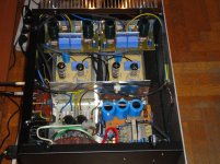
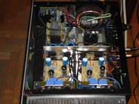
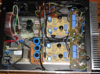
Hi to All , after a long time of experiments and troubles with different output topologies and different tube stages to drive the output stage , I finaly finish my new amp , it's a hybrid one , the first gain stage consists of one PCC85 in LTP configuration followed by a second gain stage which is the triode section of the PCL86 and the pentode section ( of PCL86 ) is the cathode follower to drive the output stage which is a class AB CFP ( Complementary Feedback Pair , also known as compound output stage ) with transistors 2SC5171 and 2SA1930 as drivers and IRFP140N - IRFP9140N mosfets as output devices .
As you see it is a very different amp from what I started to build and design in the begining , the new name of the amp is ROHH AMP , so goodbye Lunatic amp ( enough trouble with you ) and welcome ROHH AMP .
Here is some technical characteristics :
Closed loop GAIN = 27dB
NFB = -17dB
POWER : 2 * 65W at 8Ω load
2 * 98W at 4Ω
Output impedance = 66mΩ
DAMPING FACTOR = 122 at 8Ω
HIGH FREQUENCY RESPONSE 260KHZ ( -3dB )
Member
Joined 2009
Paid Member
Thanks Bigun , it sounds very good , detailed , clean and with good bass .Looks good Dimitris, tell us about the sound !
The reason is to keep as possible away the power transformers from the tubes !What's the reason to put the output/heatsink on one side of the chassis, instead of a more traditional layout - one on each side with the PS down the middle?
.Thank you very much Esteban for your kind words !Dimitris, dude you are an good example of man, I am proud of you.
Thanks for share, this is a clever idea and project
The best for you
, you are a realy good and kind man ! .- Status
- This old topic is closed. If you want to reopen this topic, contact a moderator using the "Report Post" button.
- Home
- Amplifiers
- Tubes / Valves
- SE Hybrid Amp "The Lunatic one"