Intentional. I don't want to dump unlimited current into the grid.
The 33K limits the long term average to 5ma (or 1W at the Grid).
The 1uF (above) will supply A2 maximum 100mA surges of short
duration. 1W might still be a higher average than I should have
allowed.
After the .1uF under the IXYS charges to 5V, the IXYS stays
pretty much out of the drive circuit as long as the operation
remains in Class A. Only kicking in to replace currents lost
during A2 conduction. Drive can still swing below ground.
I dunno what sort of superdrive this is? Its not like Tubelab's.
Mostly just the result trying to re-use Zobsky's existing circuit
to the greatest extent possible.
--------------------------------------------------------------------------------
I needlessly axed his LED, that part of the circuit wasn't actually
broken. Excepting that stage had more gain than could be used.
A small degenerative cathode feedback might help to re-linearize
the plate, as I had moved Zob's CCS elsewhere to get A2 going.
200R on the 12B4's grid might still be too much for good A2. 100R
or 50R, or even just a ferrite bead with no extra resistance at all.
Wavebourn said:
On short peakis.
Oh shoot. I forgot the output cathode isn't hard fixed at 30V bias.
Its caps are gonna pump up and, like Wavebourn said...
On the other hand, it would take the full maximum long term 5ma
to boost that cathode by an equal 5V. I guess it can never get to
5mA=1W over the long term, which may be a good thing.
The 33K and 1uF may then be needless? The 1K cathode resistor
and cap already providing a 5mA failsafe against long term abuse.

So draw it then! Don't pretend like you don't know how.Wavebourn said:Even better: a "Vbe multiplier" with a Zener in series with a trimpot.
Its not like you would have to scribble it on a napkin and
then go find a camera. No wait, thats... Nevermind....
I've heard Zob's amp in person, and the first Watt or
two of it sounds really good. Its not as broken as the
worst case scope traces you seen above. Just needs
a little help in the overdriven misbehavior department.
kenpeter said:
So draw it then! Don't pretend like you don't know how.
Its not like you would have to scribble it on a napkin and
then go find a camera. No wait, thats... Nevermind....
I've heard Zob's amp in person, and the first Watt or
two of it sounds really good. Its not as broken as the
worst case scope traces you seen above. Just needs
a little help in the overdriven misbehavior department.
... wait till you hear it with efficient speakers
last weekend, I compared it to a bottlehead parafeed 2a3 and as long as we didn't turn it up too high, it was not embarassed at all
Saturday, we tried the simple Mu Follower mod on one channel only.
Qty4 5uF/400V in parallel. Audible clipping seemed far less apparent.
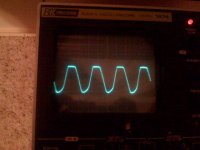
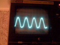
But the scope told another story: Turning up the drive still clips flat
on top, yet nowhere near as bad as before. Slowly then rounding to
a nice sine wave on top as the coupling and bypass caps pump up a
charge. Seemed like it took about 1/2 a second to get right with the
new level.
Anyways, we could then drive a continuous clean sine wave of near
three times the previously clipped amplitude, guessing by what was
seen on the scope.
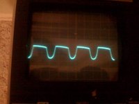
What happen on the output side of the transformer is a picture that
Zobsky will have to post later. Not pretty... Shooting us roughly the
same "finger" on both the new and original channels, so I think the
Mu Follower mod was not at fault. We were playing into a 10 ohm
dummy load, 20 ohms looked even worse. Yet with loudspeakers,
(Zobsky's Line Arrays) it sounds just fine???
It seemed to me that something unexpected was happening in his
SE iron. It may have been saturating? Thats when Zob starts telling
me about this unused 20% tap on his vintage Magnavox OPTs. He
said it was originally part of the B+ power supply. Now I wonder if
that tap was also abused by Magnavox to oppose core saturation?
Qty4 5uF/400V in parallel. Audible clipping seemed far less apparent.
But the scope told another story: Turning up the drive still clips flat
on top, yet nowhere near as bad as before. Slowly then rounding to
a nice sine wave on top as the coupling and bypass caps pump up a
charge. Seemed like it took about 1/2 a second to get right with the
new level.
Anyways, we could then drive a continuous clean sine wave of near
three times the previously clipped amplitude, guessing by what was
seen on the scope.
What happen on the output side of the transformer is a picture that
Zobsky will have to post later. Not pretty... Shooting us roughly the
same "finger" on both the new and original channels, so I think the
Mu Follower mod was not at fault. We were playing into a 10 ohm
dummy load, 20 ohms looked even worse. Yet with loudspeakers,
(Zobsky's Line Arrays) it sounds just fine???
It seemed to me that something unexpected was happening in his
SE iron. It may have been saturating? Thats when Zob starts telling
me about this unused 20% tap on his vintage Magnavox OPTs. He
said it was originally part of the B+ power supply. Now I wonder if
that tap was also abused by Magnavox to oppose core saturation?
Here's "part of" the schematic of the original application of hte OPTs . I no longer have the complete schematic but the partial winding was used as a humbucking filter. Here's an example of that application http://www.angelfire.com/vt/audio/se6bq5schem.gif .
I haven't had time yet to implement the long term fix. Will report back when I do.
I haven't had time yet to implement the long term fix. Will report back when I do.
Attachments
Hmmm... B+ is connected to the red lead right? In the original Maggie circuit the brown wire fed HT to the preamp stages (and maybe the output screens) right? Maybe if you just have the brown wire taped off right now you could run it to a resistor in series with a pot to ground and adjust it to draw about the same current that the original circuit would have drawn there and the twiddle it to see if the distortion is at all affected.
- Status
- This old topic is closed. If you want to reopen this topic, contact a moderator using the "Report Post" button.
- Home
- Amplifiers
- Tubes / Valves
- SE amp: Please suggest a better operating point