#22
Hello kenpeter,
please tell me the diyAudio feedback rules,
I am happy add them to the diyAudio technical forum rules, thanks.")
Darius
Originally #22 posted by kenpeter
...
Besides: G1>Cathode resistance is a negative feedback.
You know the rules about feedback!
Hello kenpeter,
please tell me the diyAudio feedback rules,
I am happy add them to the diyAudio technical forum rules, thanks.
Darius
#15 curve shapes
"
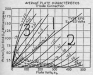
Output curve 1 shows a linear resistor.
Curve 2 shows a diode or a triode at negative grid voltages.
Curve 3 shows a pentode, tetrode etc., transistor FET BJT or a triode at
positive grid voltages.
"
Darius, I am a little confused by your hand-drawn plate curves.
You show both the "pentode" and "triode" curves converging at both ends of the resistor curve.
I'm more familiar with the attached curve which shows the plate curves asymptotically parallel with the "resistor" curve.
edit -- what I think the parallel plate curves show is relatively constant plate resistance for different grid voltages in the straight region of the curves, implying at least some of the triode-ness is retained at +ec1
This chart is for a 6F6 though. Maybe different tubes behave differently; I have not tested this myself.
Cheers,
Michael
PS
"
Output curve 1 shows a linear resistor.
Curve 2 shows a diode or a triode at negative grid voltages.
Curve 3 shows a pentode, tetrode etc., transistor FET BJT or a triode at
positive grid voltages.
"
Darius, I am a little confused by your hand-drawn plate curves.
You show both the "pentode" and "triode" curves converging at both ends of the resistor curve.
I'm more familiar with the attached curve which shows the plate curves asymptotically parallel with the "resistor" curve.
edit -- what I think the parallel plate curves show is relatively constant plate resistance for different grid voltages in the straight region of the curves, implying at least some of the triode-ness is retained at +ec1
This chart is for a 6F6 though. Maybe different tubes behave differently; I have not tested this myself.
Cheers,
Michael
PS
Attachments
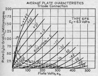
Looks like a load line placed at right angles to the 6F6 plate curves would have fairly constant gain versus grid voltage around -10V to +10V on g1 (would have to deal with the grid current though). But this could be an illusion without some finer measurements. Two obvious counter effects of compression are occuring at larger + and - grid1 voltages, but they may just produce a peaked gain curve at the center (rather than flat), giving odd harmonic distortion.
Don
Don
#26
Hello Michael,
see attachment.
Kind regards,
Darius
Originally #26 posted by Michael Koster
"
Output curve 1 shows a linear resistor.
Curve 2 shows a diode or a triode at negative grid voltages.
Curve 3 shows a pentode, tetrode etc., transistor FET BJT or a triode at
positive grid voltages.
"
...
Darius, I am a little confused by your hand-drawn plate curves.
You show both the "pentode" and "triode" curves converging at both ends of the resistor curve.
... Michael
PS
Hello Michael,
see attachment.
Kind regards,
Darius
Attachments
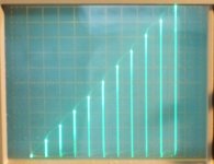
this rather old thread intimating that it is possible to achieve some linearity
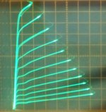
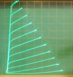
We have the technology now. "Crazy drive"
1) conventional grid 1 drive
2) "Crazy drive"
3) Crazy drive Vin to Iout on 2600 (P-P) Ohm load line
We also have "new" series Schade (UnSET, CED at Tubelab) for linear triode mode
4) "new" series Schade/ UnSET 6HJ5
5) conventional internal triode 6HJ5
Attachments
Last edited:
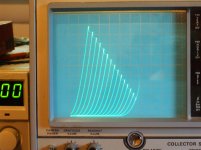
There is an RCA App note with it from way back. But no one seems to have pointed out that it can be tuned up to get constant gm until recently. A good curve tracer helps. Square root Grid 1 current through a selected series resister (and 0 Volt grid 1 biasing) removes the 1/2 from the usual 3/2 power law.
Last edited:
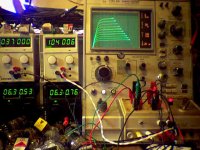
I still need to modify my old Tek 575 transistor curve tracer to use also for tubes. Funny this is an "all tube" tracer to measure transistors, what an irony..
575 - TekWiki.
575 - TekWiki.
The Tek 576 is easy to modify for tube testing. Already does HV "plate" sweeps and V steps for Fets. Just needs the "grid" stepping V range increased. (This one will now do up to 170V stepping range for grid 2 plots, can add a fixed V too, to go higher) An all SS curve tracer for tubes.
Attachments
Last edited:
- Status
- This old topic is closed. If you want to reopen this topic, contact a moderator using the "Report Post" button.
- Home
- Amplifiers
- Tubes / Valves
- screen-drive (g2 driven) plate curves spacing linear!