alexcd said:..but we're talking at least 500lbs worth.
Hmm.. GOOD!

Its OK to alter the construction.. BUT it won't be nearly the same.
You would be better served by reducing the spacing for sand to 1 inch spacing on all sides but the top, and 2 inches on the top. It would still be extremely heavy of course.. but that helps out quite a bit.
I tried to cover the need for weight in my "voodoo of vibration in loudspeakers thread" - but it doesn't seem to get through. Hmm, try reading this review on a loudspeaker - the drivers though expensive aren't terribly special (except the ribbon in its linear region), what really *makes* this loudspeaker special is the rigidity of the driver coupling and the massive amount of weight:
http://www.positive-feedback.com/Issue20/dkdesignsf7.htm
Other issues:
Note that unless you corner load the sub (and have a fairly low crossover point - say 40 Hz or less), you may experience the same problems that Shin did with max spl. On the other hand 102 db isn't exactly quiet - but this is a subjective thing and really depends on what you want. The other *possible* solution is to increase the size of the vent to about a 5 inch diameter.. but that increases length considerably.
Another thing..
With the driver closer to the ground you'll get a bit more low freq. room "lock", BUT the freq. balance may be tilted up a bit more higher in freq., requireing even more care with loudspeaker summation.
Finally..
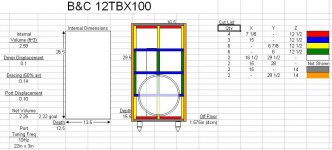
You have about the optimum volume to spl for 20 Hz at 2.25 internal cubic feet - so if you have calculated volume correctly then it should be good.
In any event - do what you want, I'm only here to make suggestions. The bottom-line is this is your subwoofer (or at least the one you are putting the sweat equity into), so only do what you feel you are capable of.
I feel a little slow but how does your suggestion about the sand apply to the driver baffle? It would obviously leak into the inner enclosure unless there was some sort of barrier. You mentioned concrete which is something I was trying to get away from doing but how is that implemented as well? I really need a visual here.
alexcd said:I feel a little slow but how does your suggestion about the sand apply to the driver baffle? It would obviously leak into the inner enclosure unless there was some sort of barrier. You mentioned concrete which is something I was trying to get away from doing but how is that implemented as well? I really need a visual here.
I'll try working on that latter today in ms paint. It'll look like cr@p though.
So give me some time and hopefully you'll be able to litterally see what I was trying to describe.
What can I do to reach 20Hz without distortion and louder than 102dB?
4 or 5" port?
larger or smaller enclosure?
I am up for any shape as long as it's not too massive. I can maybe deal with a longer port if I were to be allowed a slot style. It can face the wall, floor, room, be corner loaded, whatever you think would work best. This is going in my friend's basement so there's a lot of hard walls to bounce sound off of (and probably a lot of dampening that we need to do.)
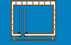
This is a side cut-away *without* the concret side baffle.. I'll get to that in a little bit.
Note that the only intended "scale" here is to show the difference between the 2 inch Top fill of sand vs. the 1 inch sides and bottom..
Key:
brown = mdf 3/4 inch
grey = bolts & spikes with support "plates"
black = vent tubeS with connection "plates", and screws (at the "but" joints of the mdf)
white = ultra fine sand
light blue = pure silicone caulk
blue = air
Attachments
alexcd said:What can I do to reach 20Hz without distortion and louder than 102dB?
4 or 5" port?
larger or smaller enclosure?
I am up for any shape as long as it's not too massive. I can maybe deal with a longer port if I were to be allowed a slot style. It can face the wall, floor, room, be corner loaded, whatever you think would work best. This is going in my friend's basement so there's a lot of hard walls to bounce sound off of (and probably a lot of dampening that we need to do.)
Well there is no such thing as without distortion..
The BEST thing is to room-corner load the sub. That will give you considerable gain without increasing excursion.
..a 4 inch or 5 inch port will require either a taller enclosure OR require some bending of the vent/pipe. Bends (particualarly sharp 90 degree bends) screw-up airflow - and it isn't something I'd generally suggest. What makes this worse is that MOST available pipe bends ARE 90 degrees.
You could actually both corner load AND have a taller enclosure made to look something like this pedestal (..and you could even build in the up-lighting like it has to use as a pedestal):
http://www.hammacher.com/publish/72000.asp
Now it *may* be the phase angle vs. impeadance or even Shin's room that is causing the "ceiling" in spl's that he is experiencing. Don't know.
If it is ultimatly power related then you could always purchase this for a bit more power and bridge it (..the lowest cost per watt):
http://www.behringer.com/EP2500/index.cfm?lang=ENG
(check elsewhere for lower prices)
If its the room then it may not be something you will experience.
Additionally remember I originally spec'ed 2 of these subs connected in parrallel - which adds almost another 6 db AND when placed correctly in the room even's out the spl through-out the room.
Interesting that you would recommend putting great effort into perfectly the enclosure and using what has been described as an extremely well constructed driver and then recommend pairing it with the "lowest cost per watt" amplifier . Do you believe the quality of amplification really matters that little with a subwoofer?
. Do you believe the quality of amplification really matters that little with a subwoofer?m0tion said:Interesting that you would recommend putting great effort into perfectly the enclosure and using what has been described as an extremely well constructed driver and then recommend pairing it with the "lowest cost per watt" amplifier
Ask yourself this:
"does lowest cost per watt = poor quality?"
What concernes me the most on an amplifier for sub freq.s is the power supply. The greater the available current, the better I like it. The greater the "instantaneous" current, the FAR better I like it.
If it were up to me the amp would have a choke loaded input power supply & and massive "reactance type" choke-out. I can guarantee you that the behringer has neither.. BUT it likely has a large bank of capacitance (and thereby current "resevoir") just to meet the large power requirements of this AB amp.
Additionally you have to factor price into the overall budget. While it may be massive construction using a relativly expensive driver - whats the cost of this? Prob. less than 450 US. What would you suggest as appropriate here, an amp costing 1000 US or more? In this instance then its a matter of practicallity - trying to achieve the "best" for the least for the given application.
Note that I'm not opposed to the idea of a 1000+ US DIY amp, its just that it doesn't seem practicle.
You definitely dont know how some people do things if you justify buying an expensive amp because you bought an expensive driver. Us common folk run out of project money and have to settle. I've heard about that amp and will recommend it to my friend. He wants to build a UCD700 but those are more expensive and I'll bust it over his head if he asks me to build one more thing for him.
alexcd said:..and I'll bust it over his head if he asks me to build one more thing for him.
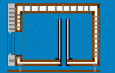
Ok, here is a side view with the concrete (actually just cement) baffle.
The Key is the same except:
Light Grey = cement baffle. &,
The little bit of orange'ish color is actual still just mdf - this time however it is 1 inch instead of 3/4 inch mdf.
(..and note that 1 inch mdf isn't really a full 1 inch - this means that the air space that is to be filled with ultra fine sand should be almost exactly the same "thickness" as the actual dimension of the 1 inch mdf.)
I'll provide a view of that orange 1 inch mdf from another perspective in the next post.
Attachments
Here is the "spacer" (orang'ish brown) portion of 1 inch thick mdf:
(..note that the ultra fine white sand is absent in the picture here.. its just the 1 inch mdf spacer on top of the 3/4 inch mdf "exterior" box panel. That same 3/4 inch mdf baffle would be on top of the cement baffle.)
(..note that the ultra fine white sand is absent in the picture here.. its just the 1 inch mdf spacer on top of the 3/4 inch mdf "exterior" box panel. That same 3/4 inch mdf baffle would be on top of the cement baffle.)
Attachments

alexcd said:Does the 1" MDF need to be square or will a circle work just as well?
A circle is fine as well - but its likely to be more work cutting the interior circle and then the exterior circle additionally.
Are things starting to look more identifiable?
alexcd said:eh... the router would already be out.
I figure all this will add 250lbs per cab.
What do mean by the router being "out"? You'll need one for the circular cuts. You could get by with them using a saber saw, but I wouldn't recomend it!
(i.e. beg, borrow, or steal one with a straight bit capable of more than 1 inch in depth.)It might add that much weight, BUT you'll have a friend helping you with the sub inversion and placement after you have finished filling it from the bottom. (..obviously you'll only fill it *very* close to where you'll be placing it.)
alexcd said:
Which side do you suggest I fill it from? I can cut a hole in the base and plug later if that's the best option.
AH!
Time to go back and read the instructions *carefully*. You don't need to cut a hole in anywhere for the filling. The bottom exterior box panel is attached last AFTER filling with sand.
Remember, while the construction is very easy (except for the cement baffle - which is not what I'd call difficult), the key is planning your build!
Urgg.. I just did some analysis of the port size needed for the additional power.
Now I'm *NOT* sure that air velocity and *actual* power work out correctly in WinIsd.
When I modeled Shins it was based on 64 watts which should provide plenty of gain considering a supposed 1 watt/ 1 meter in room nearing 87 db at 20 Hz. (..in other words at 64 watts there is a power factor increase of X6 = +18 db theoretically).
If I up the power to 256 watts AND the vent diameter to 5 inches then the program calls for 61 inches of vent length to comply with its max velocity spec.. This would make for a very high (almost 6 foot) box that is quite "thin". (..or it would require some pipe bends, or perhaps an exterior pipe.)
Again though, I'm not really sure what's happening with the power requirement vs. acoustic output. If indeed because of the impeadance vs. phase the sub is basically "p!ssing" away power - does this mean that the power vs. velocity "holds up" for the max velocity vent diameter requirement? That I can't tell you.
But hey, since RonE is more technically astute than I am - why not ping him for the answer?
- Status
- This old topic is closed. If you want to reopen this topic, contact a moderator using the "Report Post" button.
- Home
- Loudspeakers
- Subwoofers
- ScottG, check out this B&C 12TBX100 design