Re: this is
Sorry to say, but this circuit can't work...
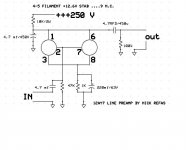
sakis said:the final schematic used and seems that performs very fine ....and square wave is very fine for at least 20khz
comments please
Sorry to say, but this circuit can't work...
Re: i apologize
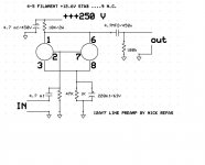
Almost correct, still a error...")
The Left 47uF capacitor is shunting the output signal to ground, it must be connected between the upper side of the 10K resistor and ground...
sakis said:it seems that it was some error in my schematic
here is the correct one
thank you
Almost correct, still a error...
The Left 47uF capacitor is shunting the output signal to ground, it must be connected between the upper side of the 10K resistor and ground...
I mentioned the need to show the input signal on your scope screen because you may have an improperly compensated scope probe.
Also, in some cases the scope can load the signal you are trying to measure...
Ought to be trivial to do 20kHz in a direct coupled tube stage, they can work into the mHz.
Btw, did you notice that this is the Solid State section?
_-_-bear
Also, in some cases the scope can load the signal you are trying to measure...
Ought to be trivial to do 20kHz in a direct coupled tube stage, they can work into the mHz.
Btw, did you notice that this is the Solid State section?
_-_-bear
yeah, i noticed it's in the solid state section.....
i used to be a Calibrator. most scope probes have either a 1Meg input impedance with a 30pf capacitance (X1 probes), or a 10Meg input impedance with a 3 to 10pf capacitance (X10). circuit loading isn't usually a problem with these probes until you get above 10Mhz. probe compensation is fairly simple, and is pretty much a "set-and-forget" adjustment.
i don't know where the myth came from that "tubes are high frequency devices, but transistors aren't" but it's a concept that's over 40 years out of date. most small signal transistors have Ft's in excess of 100Mhz (even the "lowly" 2N2222, which has an Ft of 200Mhz). modern power transistors have Ft's in the range of 3 to 100Mhz. even op amps are no longer limited to the audio spectrum, as there are op amps with bandwidths as high as 700Mhz. sure, back in 1960, most transistors had Ft's of 100khz or less, but that changed rapidly between 1960 and 1970 with the change to silicon from germanium, and the perfecting of silicon processes.
- Status
- This old topic is closed. If you want to reopen this topic, contact a moderator using the "Report Post" button.
- Home
- Amplifiers
- Solid State
- scope readings