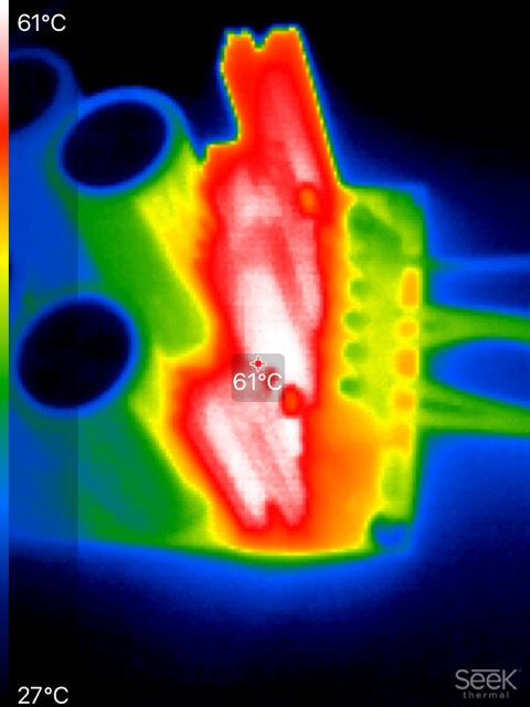
Most recently, I'm putting rectifier diodes on heatsinks and mounting those heatsinks VERY CLOSE to the electrolytic filter capacitors. Dangerously close, so close they can bake the reliability out of the caps if not very very carefully calculated.
Because of that, I've chosen to use 10-ampere Schottky diodes for their low forward voltage drop, thus low (Vfwd * Idiode) power dissipation, and because of low power dissipation: low heat. Thermal camera image below.
Since a C+RC snubber across the transformer secondary can eliminate all ringing, I haven't felt the need to specially select a diode whose recovery characteristic is softer than a Schottky's. The C+RC is cheap, reliable, and high performance ... while the Schottky diode's Vfwd is unbeatably low.
Of course all of the above is my opinion and if you happen to hold a different opinion: good on YOU.
datasheet of Schottky diode
technical article about diodes and transformer ringing
A few tid-bets, hopefully useful:
Close is good, but heat is bad. Have you thought about a shield? Is there airflow past the heat sink through the chassis and top?
Half an Ohm between the caps does wonders for ripple.
MOV on the secondary side? Never seen that before. Usually it is used just past the input fuse on the mains. They are not fast enough to do anything on the secondary and their failure mode is a short, so they must be fused. Every transient they take causes them damage.
Snubbers are best soldered right at the secondary windings.
Just looked up some of the 10A diodes like DST2045C .58V drop. I was not aware of any below .8. Something for sure to keep in mind. Thanks for that tip.
An ideal rectifier will eliminate almost any heat (way lower Uf than Schottky diodes, think of 60 mV) and thus makes it possible to group rectifiers and caps practically together. I calculated and measured this very carefully. After various comparisons I decided to upgrade nearly all single linear PSU's of sources/DACs etc. with ideal rectifiers. I built an amplifier with an LT4320 based rectifier that also tested better than a simple bridge.
The voltage will be higher than usual but that is not critical in most cases. They are expensive though but you won't need a FLIR so that compensates a bit
The voltage will be higher than usual but that is not critical in most cases. They are expensive though but you won't need a FLIR so that compensates a bit
Last edited:
An ideal rectifier will eliminate almost any heat (way lower Uf than Schottky diodes, think of 60 mV) and thus makes it possible to group rectifiers and caps practically together. I calculated and measured this very carefully. After various comparisons I decided to upgrade nearly all single linear PSU's of sources/DACs etc. with ideal rectifiers. I built an amplifier with an LT4320 based rectifier that also tested better than a simple bridge.
The voltage will be higher than usual but that is not critical in most cases. They are expensive though but you won't need a FLIR so that compensates a bit
Curious device. So you need an expensive controller chip and 4 MOSFETS.
So, what tested better in your amplifier? Was it a linear supply or an SMPS. I can see their advantage if automated assembly so no hand assembly of heat sinks and hardware. If someone made a 4-pin GBPC or KBPM package with the MOSFETS built in, I might be impressed. Anyone know of such a device?
I haven’t seen it mentioned in this thread yet so I’ll drop a note for the unaware: search the forum for quasimodo and cheapomodo and then give a big thank you to Mark Johnson!
Great thread if you were designing a lot of power supplies with a lot of different transformers. For a one-off, we are stuck with trial and error. Toss a .01 at it and a few different resistors and see what it looks like in operation. Hand grenades and horse shoes.
Curious device. So you need an expensive controller chip and 4 MOSFETS.
So, what tested better in your amplifier? Was it a linear supply or an SMPS. I can see their advantage if automated assembly so no hand assembly of heat sinks and hardware. If someone made a 4-pin GBPC or KBPM package with the MOSFETS built in, I might be impressed. Anyone know of such a device?
Curious post, please reread my post. And yes they are available here on diyaudio from a few members and some are indeed in a format that makes them compatible in a lot of devices. Their performance is what should impress though. Almost no heat, ultra low Uf (or Vf) and mucho Ampere.
Last edited:
I got caught out with a valve audio mixer and diodes.
I put in 1n4007's as it was about 200 volts rectified voltage.
I got a nasty buzz through the speaker.
I scoped the power supply and huge short spikes as the diodes switched.
So bought in some schottky's and that fixed the problem.
I put in 1n4007's as it was about 200 volts rectified voltage.
I got a nasty buzz through the speaker.
I scoped the power supply and huge short spikes as the diodes switched.
So bought in some schottky's and that fixed the problem.
Lower heat. I get that. Smaller spikes, sure. You imply the amplifier performance was better. What is better about the amplifier?
UF or VF? Nothing that a proper filter bank won't take care of. Less disturbance going back out the line? Yes, all for that. I am looking for a reason to try them other than you did and believe them to be superior. I get that, just give me the details. My old DAC has an external supply I recently rebuilt. I split the filter bank with a 10 Ohm resister and it recused the ripple by over 10 dB. It would be a good test case to see of the actual output could be improved. I added a LT1073 regulator with a 680p silver mica on the output as a pre-regulator. I assume a 317 or similar internally which may make more noise than the external supply. Noise floor is in the -115 dB range with barely a hint of 120 hz.
Available "here". Not in the DIY store I could find. Could you point me?
Nigel,
What was the condition of your supply caps? Any electrolytic over about 7 years old has gone to hell. So swapping the rectifier may be just reducing the problem other parts were allowing due to age. I bet it did not buzz when new. Does your supply have good HF bypass caps?
What was the condition of your supply caps? Any electrolytic over about 7 years old has gone to hell. So swapping the rectifier may be just reducing the problem other parts were allowing due to age. I bet it did not buzz when new. Does your supply have good HF bypass caps?
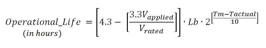
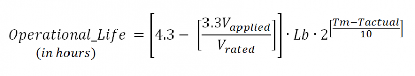
For those who are REALLY interested in temperature-accelerated failures of electrolytic capacitors, I recommend this excellent application note by Cornell Dubilier: LINK 1
It contains their Arrhenius model of capacitor lifetime:
Let's use the capacitor and the temperature data in post #41 above, to work out an example.
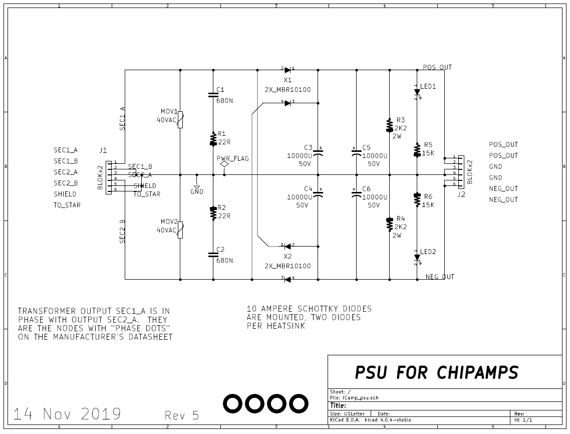
1. The capacitors on that PCB (25mm diameter, 10000uF, 50V) are Cornell Dubilier 380LX103M050J052 (DigiKey link).
2. The sales information on the DigiKey page says "3000 hours @ 85C"
3. Let's assume the SeeK thermal image is incorrect by 2 degrees, and the capacitor temperature is really 63C, not 61C as displayed on the image. So "Tactual" in the model is 63C.
4. The operating voltage in the LM3886 ChipAmp application is 32VDC ("Vapplied" in the model) and the capacitor rating is 50V
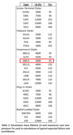
5. Looking at the handy table provided by Cornell Dubilier and attached below, for this 380LX capacitor, Lb=5000 and Tm=90
6. Plugging these numbers into CDE's mathematical model gives: Operational_Life = 71 thousand hours. Not bad for a "3000 hour" capacitor.
7. And the reason WHY it's so good, is: we used Schottky rectifiers. They heat up a lot less than other rectifiers because their Vfwd is a lot lower.
_
It contains their Arrhenius model of capacitor lifetime:
Let's use the capacitor and the temperature data in post #41 above, to work out an example.
1. The capacitors on that PCB (25mm diameter, 10000uF, 50V) are Cornell Dubilier 380LX103M050J052 (DigiKey link).
2. The sales information on the DigiKey page says "3000 hours @ 85C"
3. Let's assume the SeeK thermal image is incorrect by 2 degrees, and the capacitor temperature is really 63C, not 61C as displayed on the image. So "Tactual" in the model is 63C.
4. The operating voltage in the LM3886 ChipAmp application is 32VDC ("Vapplied" in the model) and the capacitor rating is 50V
5. Looking at the handy table provided by Cornell Dubilier and attached below, for this 380LX capacitor, Lb=5000 and Tm=90
6. Plugging these numbers into CDE's mathematical model gives: Operational_Life = 71 thousand hours. Not bad for a "3000 hour" capacitor.
7. And the reason WHY it's so good, is: we used Schottky rectifiers. They heat up a lot less than other rectifiers because their Vfwd is a lot lower.
_
Attachments
Last edited:
Nigel,
What was the condition of your supply caps? Any electrolytic over about 7 years old has gone to hell. So swapping the rectifier may be just reducing the problem other parts were allowing due to age. I bet it did not buzz when new. Does your supply have good HF bypass caps?
It was a brand new valve audio mixer.
The PSU only had electrolytic's in it.
Yup, 8 years. 63 is darn warm, but the 7 to 10 is still a valid concept.
What their chart does not show is time alone. They do degrade just by time.
If you plot the bathtub curve, you will get that same result. My concept of life is before the rise, not 20% up it.
Store them on the top level of a High-Bay in Colorado for 6 months, and the life is a lot less. 10 years in failure analysis, we looked at problems like that.
In a round of maintaining my old stuff, I found it difficult to find still available caps in the similar form-fit. A few brands are recommended, ELNA for example, but not so much series. For example, the big cans in my MOSFET amp are only available as NOS for $100 each. They are shorter than most. I have not found replacements that physically fit in my Nakamichi PA5. Also short and fat.
Here on the bench is a tube hybrid preamp with high internal temperature AND regulators oscillating because ultra low ESR caps were used. Even fake Nichicon FW caps are used and these are shot.
So now the challenge was finding normal electrolytic caps that are 105 degree rated. Probably should have put more time in it but I ordered new Nichicon FW which are 85 degrees rated. When measured the old ones were 45 degrees Celsius. Only 2 were over 50 degrees so I used larger heatsinks on the regs.
Theory is nice but it seems not every designer uses it
Last edited:
The regulators most susceptible to oscillation with low-ESR caps, are the ones whose series pass transistor is configured as a common-emitter stage: namely with the V_pos_regulated taken from the collector. "Low Dropout Regulators". Integrated Circuit Low-Dropout-Regulators usually tell you, right on the datasheet, what ESR to use and what ESR to avoid.
Sometimes the datasheet fails to scream about it loudly enough to get every customer's attention, and then some customer builds a circuit which oscillates, and then the customer screams at the IC manufacturer, and then the IC manufacturer rushes to print an application note like the two I have attached below. There! Now customers have no excuse if they use the wrong caps.
_
Attachments
Playing with LTSpice. At least on the LT1083, third leg current matters and it is not the same as a 317!
Interesting the papers comments on stability caps. They say you tend to get more stability issues with generic aluminums rather than low ESR which is why they suggest Tantalum or others. Going way too large can get you into trouble though.
Using the simulation, how much it compares to reality not sure, but I get half the 120hz ripple with silicon rectifiers than I do with Schottkys. I do get the higher first and second cycle current as one would expect with lower FV. Only way to learn more is to order some parts. LT models on some "slow" diodes may not be the best as that is not their thing. I have not re-integrated my old libraries.
- Status
- This old topic is closed. If you want to reopen this topic, contact a moderator using the "Report Post" button.
- Home
- Design & Build
- Parts
- schottky vs. soft/fast recovery diodes