Try reversing BOTH inductors. Try it with the points of the coils facing out. And the phase dots reversed from where they are. I.E., the phase dot on the primary away from the plate and opposite on the secondary.
No cigar.
Think i am going to clock off so don't be surprised if it goes quiet. Hopefully a few suggestions will drift in over time.
Shoog
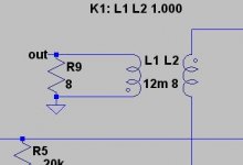
Heres what gives me the error
Shoog
try removing the "L" at the end of the inductors' values. Of course, a better way to do it, is to use the drop-down transformer models from Intact Audio Forum.
Last edited:
 Thanks very much for the link.
I got a model to work in the end.
I rebuilt the model from scratch starting with the transformer (an ultralinear model) tested it and then added components in stages - testing at each stage. Having fun.
An interesting finding so far is that it simulates such that a larger screen resistor decreases distortion considerably - which runs counter to what I had been told.
Shoog
Good, I wish I could have been more help. I've been running simulations since last Sunday. Something I've noticed is that sometimes you run the simulation and the counters all work except the percentage progress. I've seen this before on iterative statistics programs. When it does I save the file, close Spice and reopen it and then the schematic and it runs.
What is really cool is you can find voltages, current and distortion anywhere in the circuit.
What is really cool is you can find voltages, current and distortion anywhere in the circuit.
Hello Everyone,
I just finished biasing the amp. Right now its biased at 80 ma. The data sheet calls for 87 ma at 400 volts. As I approached 87 ma the amp began to oscillate. The same sort of sound when you have to much feedback. I think its called motor boating? But if it starts to oscillate at 87 ma will it oscillate as soon as I play music through it when biased at 80 ma?
Kevin
If the above proves not to be true the other potential issues are unintended feedback through the power supply, noting that most high voltage electrolytics have significant ESR and ESL at frequencies above a few kHz.(Assuming you have enough capacitance at LF) Finally as plate current goes up so does transconductance, it may be that there is enough phase shift inside the loop to cause problems as the OLG increases - if this is LF related (motorboating) this likely indicates coupling through the supply, if it is HF related then a step network (lag compensation) from 6688 plate to ground may help to compensate for HF phase shift inside the loop - alternately you could just increase the value of the schade feedback resistor until (and if) the problem goes away.
I'm an idiot sometimes. Or as my mother used to say an 'idgit'. I didn't even have a grid resistor on the 6550 G2. I tried some different resistors in spice and they all drove distortion up with large values so I tried a 200 ohm resister and that took care of the problem. On turn on the 6688 filaments flash. So I'm going to try a CL60 thermistor in the 6688 filament circuit.
I'm an idiot sometimes. Or as my mother used to say an 'idgit'. I didn't even have a grid resistor on the 6550 G2. I tried some different resistors in spice and they all drove distortion up with large values so I tried a 200 ohm resister and that took care of the problem. On turn on the 6688 filaments flash. So I'm going to try a CL60 thermistor in the 6688 filament circuit.
Flashing filaments are not an issue - but a thermistor will be added insurance.
Shoog
- Status
- This old topic is closed. If you want to reopen this topic, contact a moderator using the "Report Post" button.
- Home
- Amplifiers
- Tubes / Valves
- Schade SE 6550