What if we do not need an amplifier with 50 watts of power but are satisfied with the 25 or so watts most Firstwatt designs have. What would have to be changed in the circuit to use the very common IRFP240 mosfet in the new circuit with the schade feedback and or would it have the SET curves? I am just a solder slinger and not a designer nor do I have or use the software to design circuits. I wonder if this is the circuit in the new F7 Nelson was talking about in the 6Moons article. I do like SE circuits over PP.
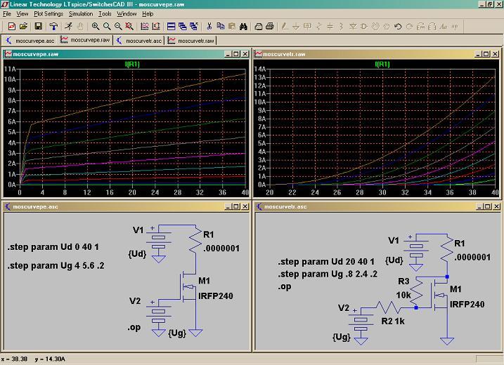
if you search for original post (Papa mentioned , but I also forgot who originally contributed that**) with IRFP240 Shade recipe , you'll see that resistor values are 1K signal to gate , 10K drain to gate
no other gate (stopper) resistors
just be careful with biasing
** found it - revintage is one to blame for that useful trick to sand parts
no other gate (stopper) resistors
just be careful with biasing
** found it - revintage is one to blame for that useful trick to sand parts
This thread will surely assist you with something to build
http://www.diyaudio.com/forums/analog-line-level/206532-if-you-dont-have-sit-fake.html
http://www.diyaudio.com/forums/analog-line-level/206532-if-you-dont-have-sit-fake.html
if you search for original post (Papa mentioned , but I also forgot who originally contributed that**) with IRFP240 Shade recipe , you'll see that resistor values are 1K signal to gate , 10K drain to gate
no other gate (stopper) resistors
just be careful with biasing
** found it - revintage is one to blame for that useful trick to sand parts
Thanks Zen, I assume there is nothing wrong with having the mu follower with a IRFP240 like Papa did in the video. If I am wrong correct me.
This thread will surely assist you with something to build
http://www.diyaudio.com/forums/analog-line-level/206532-if-you-dont-have-sit-fake.html
This is all new to me, thanks.
I am lucky to have some of the V-Fets and actually have a board for one of the earlier designs but I am waiting for the SE design Papa has promised. This Schade circuitry just peaked my curiosity and it would be a great project to build and see how it performs. Maybe one day. Then maybe someone else that does not have the V-fets will jump in the water.
A SIT sounding amplifier using common available mosfets, what's there not to like.
A SIT sounding amplifier using common available mosfets, what's there not to like.
Last edited:
With schade feedback we have now different curves, ok. But what does it mean for the real performance? Lower distortion? Or different THD spectra? Do we also have lower gain with schade?
nothing wrong in observing Papa's BAF lecture again

Here's another thread that may be of interest. The latest "L'Fake" played sweetly at Burning Amp 2015 this past Saturday. I flatter myself to think that it was possibly the ugliest amp (in appearance) displayed there....
http://www.diyaudio.com/forums/pass-labs/220110-lfake-cheap-expedient-replace-elusive-sit-2.html
http://www.diyaudio.com/forums/pass-labs/220110-lfake-cheap-expedient-replace-elusive-sit-2.html
Member
Joined 2009
Paid Member
Re: Shade around IRF240: I don't think it's anything other than negative feedback. In the Schade case, when you have only one MOSFET it looks rather 'local' in nature. I suspect you need to put an output transformer into the Drain circuit to have any chance it might remind you of a SET ?

You can do fake SIT amps both with and without transformer coupling. The thread cited by me a couple of posts ago shows transformer-less amps (but with output coupling cap. The thread shown below describes an amp that used output transformers, much in the manner of a classic pentode-based tube SE amp.
http://www.diyaudio.com/forums/pass-labs/215534-das-ist-aber-schade.html
http://www.diyaudio.com/forums/pass-labs/215534-das-ist-aber-schade.html
Member
Joined 2009
Paid Member
Not really - the amp in question is sitting in the basement waiting in line to be fitted with some higher quality 3k output transformers, which will allow better power transfer and (perhaps) lower distortion. This amp is also ripe for a version using the Cree SiC mosfets.
I have lots of irons in the fire, so I tend to bounce between project quite frequently. Quite often what I learn in the process causes a project to morph radically compared to its earliest conception.
I have lots of irons in the fire, so I tend to bounce between project quite frequently. Quite often what I learn in the process causes a project to morph radically compared to its earliest conception.
Here's the latest version of L'Fake that "graced" Burning Amp 2015 this past Saturday - ugly, but quite functional.
http://russbutton.com/Russ/audio/2015BurningAmp/20151017_111624.jpg
http://russbutton.com/Russ/audio/2015BurningAmp/20151017_111624.jpg
I've seen the schade circuit before without know what I was looking at. I thought it was just feedback not that it would make a mosfet have curves like a SIT. It's good to learn new things.
How about some descriptions of what these new designs sound like from the BAF attendees. Where are you 6L6, Mike, etc ?
How about some descriptions of what these new designs sound like from the BAF attendees. Where are you 6L6, Mike, etc ?
I actually used Schade feedback in the "Half Nelson" amp that showed up at BA 2007 without having any idea that it could emulate a SIT.
http://www.diyaudio.com/forums/pass-labs/114167-half-nelson-amp.html
http://www.diyaudio.com/forums/pass-labs/114167-half-nelson-amp.html
Last edited:
Here's the latest version of L'Fake that "graced" Burning Amp 2015 this past Saturday - ugly, but quite functional.
http://russbutton.com/Russ/audio/2015BurningAmp/20151017_111624.jpg
Hello wrenchone. Your prototype is a beauty compared to the transient ones I regularly assemble, and disassemble.
I had followed wrenchone's threads with high interest. My "Schade'd" prototype with BJTs seemed to have a discernible subjective performance which was different from the un Schaded" parent.
Like other DIYers, I'd love see a thread by wrenchone revived. No doubt new ones will be started based on the talk of Mr. Pass at BAF2015.
- Status
- This old topic is closed. If you want to reopen this topic, contact a moderator using the "Report Post" button.
- Home
- Amplifiers
- Pass Labs
- Schade circuit using IRFP240's