")
Help with PS2.2 issue
I am trying to use a 65v PS2.2 in a regulated front-end amplifier project, but run into a short circuit condition when putting the main rectifiers in series.
The main power torroid is a dual secondary (50-0 50-0), to which a pair of bridge rectifiers are connected. Simple enough. AC in, DC out. No DC smoothing caps for now, just a measured voltage out.
If I series connect the negative terminal of one bridge rectifier to the positive terminal of the second rectifier, I get double the DC voltage at the remaining terminals. Series voltage, common sense.
Remove the DC series connection for now...
To power the 65V PS2.2, I now add a second torroid - dual secondary 6-0 6-0, in series with the main torroid. (50+6 - 0, 50+6 - 0). Each regulator has its own isolated AC input. The regulators start right up and supply the prescribed DC output. No problem here...
.... until I add the series connection for the bridge rectifiers back in. My light bulb tester, in series with the transformer primaries, turns blindingly white - indicating a short circuit now exists. But I don't see where (or why) this occurs. I have verified the bridge rectifier pin outs, but have no other ideas.
There is no difference if the PS2.2 DC common is connected to the rectifier series junction or not. Which is where I need it eventually. Any ideas on cause or solution?
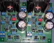
Attachments
Hi Jens,
Thank you.
I pulled DC out from the rectifiers directly to the (fuse protected) leach VCC/VSS inputs, as I have 6800uF caps on-board. For testing purposes, this should be sufficient.
I have tied Positive regulator and Negative regulator grounds together. The central ground point is where the two bridge rectifiers join together.
For clarity, I do not have the Leach pcb connected while I sort out this power issue. Once the bulb lit, I pulled the wires leading to the board.
Thank you.
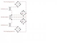
Per the jpeg schematic, have I kept the AC seperated? 50-0 secondary to rectifier. Additional 6-0 secondary series connection to PS2.2 AC input.Keep the AC seperated
PS2.2's DC out will go to the front end only, once I verify function.ONLY connect the DC output to the amp
I pulled DC out from the rectifiers directly to the (fuse protected) leach VCC/VSS inputs, as I have 6800uF caps on-board. For testing purposes, this should be sufficient.
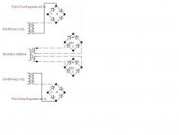
the "gnd" on the positive regulator should go to your central ground
I have tied Positive regulator and Negative regulator grounds together. The central ground point is where the two bridge rectifiers join together.
For clarity, I do not have the Leach pcb connected while I sort out this power issue. Once the bulb lit, I pulled the wires leading to the board.
Hi Jens,
I see the changes. However, the PS2.2 is set for 70V output.
Isn't there a saying "What come out, must go in..." maybe it was an American song from the 60's about up and down, I dunno.
Anyhow, I need to stack the AC voltages on the regulator input to obtain 70vDC.
I have two torroids, each with dual secondarys. T1 = 50-0, 50-0, and T2 = 6-0, 6-0. It seemed logical to series a 50v with a 6v for the PS2.2 AC input.
6vAC alone will not provide much DC for Leach.
Maybe I missed the point. In looking at applying AC to multiple rectifiers, I don't follow where a short circuit condition is created. It appears that I should get DC at multiple points...
Stacking the AC voltages should then provide multiple DC voltages. In my case, this is neither scientific princliple or common sense
I see the changes. However, the PS2.2 is set for 70V output.
Isn't there a saying "What come out, must go in..." maybe it was an American song from the 60's about up and down, I dunno.
Anyhow, I need to stack the AC voltages on the regulator input to obtain 70vDC.
I have two torroids, each with dual secondarys. T1 = 50-0, 50-0, and T2 = 6-0, 6-0. It seemed logical to series a 50v with a 6v for the PS2.2 AC input.
6vAC alone will not provide much DC
for Leach. Maybe I missed the point. In looking at applying AC to multiple rectifiers, I don't follow where a short circuit condition is created. It appears that I should get DC at multiple points...
Stacking the AC voltages should then provide multiple DC voltages. In my case, this is neither scientific princliple or common sense
rob3262 said:Hi Jens,
I see the changes. However, the PS2.2 is set for 70V output.
Isn't there a saying "What come out, must go in..." maybe it was an American song from the 60's about up and down, I dunno.
Anyhow, I need to stack the AC voltages on the regulator input to obtain 70vDC.
I have two torroids, each with dual secondarys. T1 = 50-0, 50-0, and T2 = 6-0, 6-0. It seemed logical to series a 50v with a 6v for the PS2.2 AC input.
6vAC alone will not provide much DC
Maybe I missed the point. In looking at applying AC to multiple rectifiers, I don't follow where a short circuit condition is created. It appears that I should get DC at multiple points...
Stacking the AC voltages should then provide multiple DC voltages. In my case, this is neither scientific princliple or common sense
Rob,
I missed the 6VAC on your drawing... sorry.... you should watch the phase of your AC when you "add" them... I recommend thinking about the point of using a regulated supply for the front end that actually sits on something floating... I think a pure 70V supply for the front end is better?
\\\Jens
Jens,
When adding auxiliary windings in a transformer to the main winding to achieve higher frontend voltage how do you determine the phase. In most cases the net voltage reading is all that is available.
I too have looked into using the psu2.2 as a regulator for my leach amp. The net on the frontend would be approximately 82 volts. I am using a 12 volt auxiliary winding from the main 1 kva transformer.
Tad
tryonziess said:Jens,
When adding auxiliary windings in a transformer to the main winding to achieve higher frontend voltage how do you determine the phase. In most cases the net voltage reading is all that is available.
I too have looked into using the psu2.2 as a regulator for my leach amp. The net on the frontend would be approximately 82 volts. I am using a 12 volt auxiliary winding from the main 1 kva transformer.
Tad
Tad,
The easy way, without a scope, is to look at the winding direction on the torride.... that will tell you the direction for the aux winding to work correctly.
\\\Jens
Hi Tony,
Go here for schematics:
http://www.noermoelle-rasmussen.dk/Delta-audio.com/PSU_TWO/PSU_DIY_ver_2.2_SCH.pdf
\\\Jens
Go here for schematics:
http://www.noermoelle-rasmussen.dk/Delta-audio.com/PSU_TWO/PSU_DIY_ver_2.2_SCH.pdf
\\\Jens
When adding auxiliary windings in a transformer to the main winding to achieve higher frontend voltage how do you determine the phase.
you can use a dmm set to read ac volts, you know you got the phasing right when the voltage you get is higher, say you have 55volts ac from center tap on main winding, then the added winding should read higher, if you added a 12 volt winding on top of the 55 volt one then the reading from center tap should now be 67.....
Late Build
Sorry for bringing this thread back into circulation. But I need some help if anyone is still reading this.
I have just started to build my 6 transistor Jens Rasmussen Leach amp (from 2005/6) and I was planning to use the PSU 2.2 unit (65V version) of this thread as my regulator. So I have a couple of questions to start with.
Cheers, Fred
Sorry for bringing this thread back into circulation. But I need some help if anyone is still reading this.
I have just started to build my 6 transistor Jens Rasmussen Leach amp (from 2005/6) and I was planning to use the PSU 2.2 unit (65V version) of this thread as my regulator. So I have a couple of questions to start with.
- The transformer that I have for the Leach is a CT 39.8-0-39.8. Is this transformer appropriate for use with this PSU assuming that the directions for use of a CT in an earlier post #176 (page 18) are followed?
- If it is appropriate, I understand the tieing together of AC1-1 and AC2-1 and AC 1-2 and AC2-2 and where they hook into the PSU board. But the only place that I see to attach the CT wire of the transformer to the Ground Plane is the unmarked posts of V+Out and V-Out. Is this the correct access to the Ground Plane?
Cheers, Fred
1. 40 VAC gets you ~55V, which is appropriate voltage for the main supply, but not enough to get you to 65V for the front end. You might try a voltage doubler as shown in http://www.passdiy.com/pdf/a75p2.pdf to feed the regulator. If you want to go that route we can discuss how to create a doubler to work with with this circuit board. Otherwise, you could use a separate 50-55V transformer or add auxiliary windings to your main transformer to give you another 10-15 VAC.
2. If using a center tapped transformer, you must not use D2, D4, D12 and D14. Repeating that just because you didn't state it.
A better grounding practice would be to return the center tap and the regulator grounds to a star ground, where you also connect the Leach amp's ground leads.
2. If using a center tapped transformer, you must not use D2, D4, D12 and D14. Repeating that just because you didn't state it.
A better grounding practice would be to return the center tap and the regulator grounds to a star ground, where you also connect the Leach amp's ground leads.
- Status
- This old topic is closed. If you want to reopen this topic, contact a moderator using the "Report Post" button.
- Home
- Group Buys
- Scalable PSU/regulator GB