Similar problem
Using the same schematic as alvinlim (RJM v1.3) (i.e. all same values/components) I have 87.7mV offset when the amp is warm. To measure this, I am placing a 10.3 ohm resistor across the output with nothing across the input. R2 is 22.03K ohm and R4 is 22.05K ohm, so they seem fairly well matched, and I was under the impression that this was the source of DC offset. There seems to be a lot of troubleshooting info for the inverting GC, but the non-inverting version has less info. Also, when wiring up the chip, I made a bad connection and it would not work and got hot pretty quick the first time I fired it up, so there is the possibility of internal damage, although I hear no audible problems when listening to it.
Where else should I look to correct this problem? I am thinking it might be time to hook up the scope to see if it is oscillation, but I'm not sure what would cause this. I plan on using the same 10.3 ohm resistor across the output and no input to view this on an old Tek 20MHz scope. Is this the correct procedure for detecting the oscillation?
Thanks for the continued help of all in this forum. What a neat hobby. I still get giddy every time I turn that simple amp on and it actually works. . .
Sandy.
I plan on using the same 10.3 ohm resistor across the output and no input to view this on an old Tek 20MHz scope. Is this the correct procedure for detecting the oscillation?
Hi Sandy. I am no expert but when I was talking to somebody who has designed a lot of commercial hi-fi, he suggested that I should use a 40Mhz scope to detect any oscillation on the output.
Scope Measurements
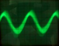
Attached is the pic of my Tek 465 reading the RJM Gainclone I built with no input connected and a 10.3 ohm resistor across the output. The signal seemed fairly noisy as well and what is seen is a well focused CRT with a lot of variation.
The scope was set at 10mV/div, so it appears that the magnitude is roughly 50mV. The time/div was set to .2us, and at roughly 4.5 divisions, the resulting peak to peak time is 9us, approximately, which would be around 100kHz. I guess this is the high frequency oscillation that victimizes some clones.
Does this analysis seem correct? Are there any other tests which would be appropriate to run?
I would appreciate any help which could be provided.
Best Regards,
Sandy.
Attachments
Nope. . .
No, I didn't short the input. I'll try running a wire from the outer shell to the inner pin if you think this is a good re-test. I'm still searching for the 86mV offset, though, and I assumed that an HF oscillation could register on my DMM as an offset.
Thanks for the suggestion. I'll try it tomorrow night and report back.
Sandy.
Second test
I tried shorting out the input to the amp and reconnected the scope, double checking that my input probe was not faulty. Upon calibration, it was a nice and true sharp square wave from the calibrator, but when I connected up to the Gainclone, it revealed the same somewhat fuzzy sinusoid at roughly 100kHz. I removed the short at the input and the wave did not change.
However, I varied the attenuator pot and at the minimum position, the signal was fairly flat, still fuzzy, but not as much. As I increased the pot, the oscillation got larger in magnitude, but seemed to remain at roughly 100kHz while on the screen. I'm not sure what happened after it went off the scope.
Where would someone suggest to chase the problem next? Proximity to the PS, component placement, component quality, component values? All resistors are 1% and measure accordingly. I have not measured cap values, but have a $40 LCR meter, so I can check them somewhat. I did make a wiring error when I first assembled the GC and could substitute a second LM3875 in its place if that is the likely culprit.
Thanks for any suggestions someone may have. I seem to have hi-jacked the thread somewhat, so if a moderator would put this into its own thread if that would be more appropriate, I would appreciate it.
Thanks!
Sandy.
Re: Second test
Easy one done , will get back to you later on the difficult stuff")
Sandy H. said:I seem to have hi-jacked the thread somewhat, so if a moderator would put this into its own thread if that would be more appropriate, I would appreciate it.
Easy one done , will get back to you later on the difficult stuff
Re: Scope Measurements
Hi,
If time base is 0.2uS then 4,5 divs resulting with ca 1MHz oscillation.
Did you insert Zobel network?
Did you try with decoupling cap (ca 1uF or so) between power pins ("1" and "4")?
Any pics?
Regards
Sandy H. said:The scope was set at 10mV/div, so it appears that the magnitude is roughly 50mV. The time/div was set to .2us, and at roughly 4.5 divisions, the resulting peak to peak time is 9us, approximately, which would be around 100kHz.
Hi,
If time base is 0.2uS then 4,5 divs resulting with ca 1MHz oscillation.
Did you insert Zobel network?
Did you try with decoupling cap (ca 1uF or so) between power pins ("1" and "4")?
Any pics?
Regards
About the offset: R2 should be close to R3 (or the value of R3 and R4 in parallel, which is 1/(1/R3+1/R4) = R3R4/(R3+R4).
Oscillation seems to happen always if gain is less than 10 (not the case here).Things like HF fluorescent light and computer monitors can cause small oscillations. Putting capacitors close to the chip is always a good idea.
Oscillation seems to happen always if gain is less than 10 (not the case here).Things like HF fluorescent light and computer monitors can cause small oscillations. Putting capacitors close to the chip is always a good idea.
Additional Info
Some additional info and pictures can be found on my site at
http://www.tshouston.net/audio/audio index.htm click on “Mic GC” button.
The schematic used was the non-inverting RJM v1.3 schematic as attached with no additional components used.
Thanks for the suggestions so far!
Sandy.
Some additional info and pictures can be found on my site at
http://www.tshouston.net/audio/audio index.htm click on “Mic GC” button.
The schematic used was the non-inverting RJM v1.3 schematic as attached with no additional components used.
Thanks for the suggestions so far!
Sandy.
Attachments
Just checking in
pinkmouse: Thanks for the initial suggestion. I will employ shorting the input for future measurements, even though this was not the solution this time. I look forward to any comments you may have from your experience to help resolve this problem
Moamps: Doh! You are 100% correct. When I first calculated the frequency, I read the scope settings, and it was 2ns. Later, when re-confirming my settings prior to posting, I noted that I had the X10 button engaged, resulting in .2ns, but I didn't take that into account when saying the oscillation was 100kHz. I did re-confirm the .2ns setting on the second test. Thanks for keeping me honest! R5 & C5 makes up the Zobel, correct? If so, I used it!
ukram: Using the schematic I built by the parallel combination of R3 & R4 yields 520 nominal ohms for R2. Is this the result you would intend for this schematic. In my neophyte understanding, I'm not 100% clear why R3 and R4 would be parallel, so I am not clear as to why this is the critical value. If I changed R2 to 520ohm, I think this would mean my input impedance would be 520ohm, not a more standard 22kohm, however I am not sure what effect this could have. I will re-read the NI datasheet and my old EE texts on op amps to try and understand this relationship. If I can't understand, I would appreciate any clarification on the reason for this calculation. Regardless, I appreciate you pointing out the relationship so I can learn more about this circuit.
In hindsight, I am seriously considering my next modification to be replacing the LM3875, as this circuit has successfully be implemented before. When I first connected the amp, my ME background allowed me to comfortable (and wrongly) assume that Vin +/- was the supply voltage, not the signal voltage. The coincidence that RJM did not indicate pin numbers on his schematic and my own oversight on confirming this with the NI sheet (which obviously stated positions) made me feel that this was the correct orientation. The result was the amp running for between 2 and 5 minutes with +/-24V on the signal inputs and +/-signal on the power inputs. If this is the result of this incorrect amp wiring, I am completely amazed at the protection circuits of the LM3875. True, not audiophile quality, but I would have expected the circuit to be 100% inoperable.
Thanks for the help. Excepting any other suggestions for possible causes, I hope to switch out the op amps to re-test and see what happens.
Thanks again. I hope you guys are all around when I try my first class A!!! I'm learning. . .
Sandy.
Next iteration
Assuming that I might have screwed up the LM3875 by miswiring it, I replaced it with a second chip. DC offset is now 116mV!!!
I checked the oscillation on my scope and it appeared to be the same, possibly with a higher peak to peak. Thinking it could be the cheap pot, I soldered a 44kOhm resistor in series with the input, bypassing the pot altogether. No change.
Then, assuming it could be a problem with my scope probes, I tried a second probe, but it did not respond well during calibration, so I was not feeling good about it. But, I tried it and the oscillation was gone, but noise was very random. I switched back to my first probe and the oscillation was gone again. I am starting to question the accuracy of my measurement system.
My next logical step will be to check the amp, as is, on a scope at work with certified probes. Regardless of the outcome, there still seems to be a large offset. Assuming the oscillation is not actual and is a phenomenon of my scope or probe, I will likely start from scratch with new components, measured carefully and go back to the original schematic, in case I made a yet to be discovered wiring error, paying close attention to the grounding scheme. If this does not solve the problem, I will see if there is a power supply variation I can try without spending too much money.
Just trying what seems logical. Let me know if anybody sees an error in my plan.
Sandy.
Re: Next iteration
Hi,
Some suggestions (inspired by your "clear" picture):
- place zobel R5/C5 on output terminals
- get input cap wire as far away as possible from + output terminal (bend up) (you use noninverting setup which is sensitive to closing input and output wires)
- insert (just to check offset voltage) a cap (ca 100uF) in series with R3 to gnd.
Scope probe has some capacitance; occasionally (RF circuits) this can attenuate signal too much or cause circuit to oscillate. In your case this is not likely, IMHO.
What are you using noninverting setup for in the first place?
Regards
Sandy H. said:[I checked the oscillation on my scope and it appeared to be the same, possibly with a higher peak to peak. Thinking it could be the cheap pot, I soldered a 44kOhm resistor in series with the input, bypassing the pot altogether. No change.
Hi,
Some suggestions (inspired by your "clear" picture):
- place zobel R5/C5 on output terminals
- get input cap wire as far away as possible from + output terminal (bend up) (you use noninverting setup which is sensitive to closing input and output wires)
- insert (just to check offset voltage) a cap (ca 100uF) in series with R3 to gnd.
Scope probe has some capacitance; occasionally (RF circuits) this can attenuate signal too much or cause circuit to oscillate. In your case this is not likely, IMHO.
What are you using noninverting setup for in the first place?
Regards
OK I think I know where your offset is comming from. The input bias current of the LM3875 is 0.2uA. Using the info given above the impedance on the inverting input is 520R and on the non inverting one 22K. Using V=IR this gives an input voltage of 520x0.2uA on one input (104uV) and 22Kx0.2uA on the other (4.4mV). Subtract one from the other to find the input ofset due to the input bias current (4.296mV) multiply by the gain of the amplifier (I am guessing about 22) gives 94mV.
The input bias can easly vairy by a factor of 5 so both of your chips were operating well within tolerance. Normally you will get no problems from offset on an amplifier below about 500mV much more than that and it might cause a significant bit of heating in the voice coil of the base driver. Still not much though.
Hope this helps. I think my calculations are correct but I am happy to be corrected if I have missed something.
Andy
I mean that you can multiply the values of both R3 and R4 so that R3 is something like 10k, and R4 about 220k. Then you should get smaller offset. Also R2 could be 10k.
I copied the formula from this page:
http://www.platenspeler.com/gainclone.html
The idea is to control bias current flowing into input transistor base. If the current is same for both inputs, there is very little offset. The offset could be adjusted by trimmer resistor R2. I'm planning to use offset trimmer in my next LM3875 design.
A sure-fire way to drop the offset by a factor of 20 is to put a cap in the ground-side of the bottom feedback resistor. That makes the DC gain x1 instead of x20.
Make sure the cap is large enough for good bass, meaning the RC product of the lower feedback resistor and the cap should be at least some 100msec.
Jan Didden
Make sure the cap is large enough for good bass, meaning the RC product of the lower feedback resistor and the cap should be at least some 100msec.
Jan Didden
ukram said:The idea is to control bias current flowing into input transistor base. If the current is same for both inputs, there is very little offset. The offset could be adjusted by trimmer resistor R2. I'm planning to use offset trimmer in my next LM3875 design.
you are absolutely correct with regards to why R2 is needed, and the guideline above can be used to select R2 (usually it is selected as the same value as R3.
However, a few other considerations here:
1) R2 cannot be too large. Otherwise, it picks up noise. This is especially important for non-inverting implementations as the (theoretical) input impendence on the non-inverting end is infinite.
2) simply grounding the non-inverting end gives the best THD+N performance.
National suggested a 3.3K for R3 but admitted that it may not be optimal. My sense is that as long as you don't venture into >50K range, it should be OK.
- Status
- This old topic is closed. If you want to reopen this topic, contact a moderator using the "Report Post" button.
- Home
- Amplifiers
- Chip Amps
- Sandy's Oscillating GC