Nothing should be changed. Its fine at 15V as it is. This not a theoretical regulator. It works very well in DACs and phones preamp in beta testing people's audio systems as we speak. If I will decide any small change in a value or a in part type for little better you will see it in the build guide when I will post it.
Well, since it is not a theoretical reg., put a DMM on its output and point a switched-ON hair dryer towards the PCB. Keep this for a 3-5 minutes and tell us what's going on.
I can do that myself but I'm too lazy to solder it - probably will ask @Selfy to do the test or at least I will arrange a meeting where we can check this together
") .
.Its a bad reg for you, don't build it then. Design your own in a way that you prefer. I know for mine what it is, how it works, how to be made different, where and why is to be used. I have my priorities in its architecture and characteristics. And my subjective preferences. Its fine for my goals and apps. I did not design it for precision purposes in harsh conditions, I won't be using it in a missile, I never claimed that. The label says simplistic shunt for a decade now. Not efficient or precision. Some people love it in audio apps not everybody else must.
If you walk carefully through my comments you won't see a word claiming it's a bad design. I'm only trying to help pointing you areas where it can be improved. And when speaking for output voltage thermal dependency, if you feed a preamplifier it COULD not be harmful for it but lets suppose the regulator is used to power a clock or something precious and fragile with requirements for power supply voltage to not exceed, lets say 5V. And if the temperature is low and the regulator's voltage goes to 6V?
Don't worry, although its not using a precision chip ref with subsurface Zener and op-amp that we would meet in a bench DMM for instance, but a simplistic unity gain Norton Vref resistors affair (with different subjective traits than high internal feedback ref chips that also need amplification in a variable reg), I have taken some synergistic tempco measures nonetheless.
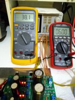
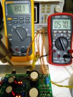
See it here doing just 0.3V drift difference over a 80.1-38.1=42C temperature delta. Which is not bad for a so simple Vref design.
The Fluke's temperature probe is sat right at the drift affecting transistors area. Using a hot air rework station's help to heat up.
42C ambient delta in an audio source or line level electronics box is not common at all. It will see 10-20C ambient temp in-box deltas at most home installed builds. There it will do smaller Vout drift from the just powered on moment to fully warmed up. Say 10.1V to 10.15V at power on will end up 10V steady when warmed up. Even such difference can be taken into account when setting up. Set it when in just started up state than in warmed up state if its for a borderline safety situation. If there is a much special reason the trimmer can be skipped and the Vrr resistor be replaced with a Zener (noisier, harsher) for a fixed voltage situation after all.
It does not do below 5V output setting anyway and it will be mostly used as a pre-reg if for digital. There will commonly be local surface mount chip regs on DACs etc. SSLVs have been used for ages serving such things and never killed anything by drift. The builders feedback in the relative threads is very high in numbers over the years so we are in a statistical position to know its safely suitable for a wide range of linear or digital audio diy applications.
Attachments
Ok, so if I have an external (unregulated DC), I could just leave the D1-D4 and all the Quasimodo stuffs empty, and feed the unregulated DC voltage directly to C1?P.S.
Have at least 100uF/50V in C1 position with any type of external DC feed. For local decoupling. Don't leave that position completely empty. Else the incoming DC leads inductance will very probably put M1 into oscillation.
Its about how they will blend with the whole application including the loading gear of course. Those non polar ES have very low THD and subjectively are clean and sweet IMHO. And hey, you can't put them wrong on the board when soldering away in the small hours
Hi Salas, I tried a few caps in a cd player a while ago and really liked Elna Silmic II. Have you compared these to the ES caps you like? I know its subjective, but would be interested your opinion. Thanks
No, not in the reg. I only had a couple of 100uF/25V Silmic II that measure 0.155Ω ESR at 100kHz and one 220uF/10V with 0.123Ω at 100kHz when I was testing. So not highly enough voltage rated samples to do the full Vout range tests. But they seem like having compatible ESR to our purpose and maybe a 47uF/50V or 100uF/50V could work for C3. Those remain to be had and measured on the LCR or applied and check if all is well on the scope regarding no rail oscillations. C2 plays no part in the termination spec as it is a Vref filter and can be freely chosen subjectively.
In general, in various audio circuits, I find the Silmic II bodily, expansive, and smooth. But bit slow and larger than life maybe. Its all about mixing different parts subjective traits well in a system though as I said before. Or its all placebo, but no worries, we do this for fun
In general, in various audio circuits, I find the Silmic II bodily, expansive, and smooth. But bit slow and larger than life maybe. Its all about mixing different parts subjective traits well in a system though as I said before. Or its all placebo, but no worries, we do this for fun
yes I know, I have often wondered if I imagine the different sound of caps, and maybe it is placebo, but it keeps me from watching reality TV, so its got to be good right
Yep, a mixing n' matching caps "sound" innocent habit is better than hardcore addiction in reality shows indeed
There's not a problem that I can't fix
'Cause I can do it in the mix
'Cause I can do it in the mix
LOL
Ok, my last question. In the schematic, you wrote about sparing 100mA > peak current.
With V1.2R, my current consumption is 110mA, and I biased the transistor at 180mA (~70mA spare)... and I was afraid that the transistor was getting too hot, so I brought down the bias to just about 140mA (so just 30mA spare).
Does this v1.3 require 100mA margin?
With V1.2R, my current consumption is 110mA, and I biased the transistor at 180mA (~70mA spare)... and I was afraid that the transistor was getting too hot, so I brought down the bias to just about 140mA (so just 30mA spare).
Does this v1.3 require 100mA margin?
Ok, my last question. In the schematic, you wrote about sparing 100mA > peak current.
With V1.2R, my current consumption is 110mA, and I biased the transistor at 180mA (~70mA spare)... and I was afraid that the transistor was getting too hot, so I brought down the bias to just about 140mA (so just 30mA spare).
Does this v1.3 require 100mA margin?
Its not a requirement but a recommendation. You probably had high Vout and small sinking to go hot with just 70mA spare. Or the average load consumption was much lower than its 110mA peak.
I like the mini Reflektors very much to use in small places, are there any plans to create mini SSLV1.3 UltraBiB's ?
No plans right now lets see how this one goes with plug-in directly upgrading for BiB people first, but I will possibly examine a DCin/DCout only, smaller size version in the near future.
Salas suggest to me to try a 390 Ohm parallel to 1K (R9), for experiment acoustic reasons. A total 280 Ohm on R9.
Hmm, very interesting experiment!
After, two days of tries to an analogue dac output (symmetrical 15V) and as a pre-regulator (positive 8.1V) on AK4490 dac, I prefer the 1K vs 280 Ohm, especially on role of pre-regulator on a digital equipment.
Sorry, I am not familiar to lyric description in the English language, because my English are bad!
But, with a less words something like more spatial "air" was the strong sign of 1K R9 that with 280 Ohm R9 was decreased.
Hello Lemon. Thanks for your beta testing reports. As I have given to you first testing guys an initial 1K R9 "safest" value (which I use for very high spare current stability up to 0.6A) but I had also tested the reg stable down to 270R when with normal 50-150mA spare currents, I then wanted to know if you have some subjective inclination about R9's value too as it changes M2's damping and phase margin. Vgeorge and DimDim checked that too, on analogue preamp with headphones and on Soekris DAC with near field speakers, and from their impressions and different leanings including your input my conclusion is I will finally suggest a middle of the road 470R value for general use. I will update it in post #1's schematics now.
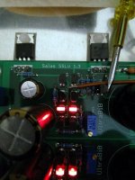
P.S. Those 1K R9s on very first test board can be seen in my post #30 photo if you look closely at the color bands of the green bodied resistors at M2s gate pins
P.S. Those 1K R9s on very first test board can be seen in my post #30 photo if you look closely at the color bands of the green bodied resistors at M2s gate pins
- Home
- Amplifiers
- Power Supplies
- Salas SSLV1.3 UltraBiB shunt regulator