One quick question regarding the Teabag IRF+ kit parts. There is one light blue colored resistor and my DMM it shows as 000.3 ohms and I presume this is 330mOhms to be used for 'Rf' (low inductance). My DMM can show only single decimal so wasn't sure as I am building the Ultra BiB for my Soekris DAC to replace the 1.1 version.Thanks
In ynmichael's post #899 first photo there are light blue MOX resistors in the Rf positions. Can they be those you are talking about?
What's the purpose of a shunt regulator? Noob here
Has the same purpose as all regulators. Just another way to regulate voltage rails. Has the output power element in parallel to the load thus it drops all of its voltage across and its wasteful for power. With no element in series its also somewhat different for electrical damping.
In ynmichael's post #899 first photo there are light blue MOX resistors in the Rf positions. Can they be those you are talking about?
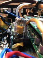
Yes Salas I think that is the one, light blue one next to the big cap near the AC side which is the 'Rf' marked on the PCB. The kit came with the same resistor by teabag and my DMM shows 000.3ohms.
Thanks
Last edited:
Has the same purpose as all regulators. Just another way to regulate voltage rails. Has the output power element in parallel to the load thus it drops all of its voltage across and its wasteful for power. With no element in series its also somewhat different for electrical damping.
Super interesting! Keep it up!
Yes Salas I think that is the one, light blue one next to the big cap near the AC side which is the 'Rf' marked on the PCB. The kit came with the same resistor by teabag and my DMM shows 000.3ohms.
Thanks
Being a noob I was confused too. But there's only 1 resistor in the kit BOM so it has to be Rf. Looking back it was strange that he chose 350ppm parts, but it probably has negligible effects where it is.
Just finished a couple of major repairs... Don't forget to connect the GND on Amanero to ISO GND, even if you connected a power source GND to it already. Otherwise you'll be scratching your head at random clicks for a very long time. Also completed the ground loop breaker circuit. Unnecessary but just might be useful when connected to some other device in the future.

Attachments
I'm in the same train as well !And to you also Salas! The next batch of GB is sold, are you ready for endless support?! Sorry, I'm one of those guys
Not many choices in stock other than MOX for that axial power resistor I would assume. The Rf position is in the raw supply side, not demanding anyway.
Merry Christmas to all you guys
Lower PPM ones do seem expensive and somewhat rare, though Rf value has a wide recommended range. In any case, if it's not on important circuit paths, we users should really do ourselves a favor and forget about it.
The UltraBiB (and the finally finished dam1021 build) was a very nice Christmas present for me. Thanks Salas! I got the one remaining board that Teabag had before the 2nd GB - early Christmas for me. I'm sure others in the GB would share the gratitude and warm feelings
Hopefully my experience documented in this thread is somewhat useful to others - Salas helped a lot with CC calculations and component selection. The build was pretty straight-forward. Not much improvisation needed with the detailed build guide. Trimming all the resistor legs was probably the most time-consuming... Probably a good idea not to do it one-by-one. One interesting thing to note is that the 5W 25R dummy load burned really hot and started smoking pretty quickly, even though the heat dissipated was less than 5W for sure. Also tweak VRR to an approximate range before you power up especially if you have a lower target voltage, e.g. 9V, otherwise the dissipated power on the dummy load might exceed the maximum.
One interesting thing to note is that the 5W 25R dummy load burned really hot and started smoking pretty quickly, even though the heat dissipated was less than 5W for sure.
That sounds a bit odd - maybe the resistor rating is not quite on.
Shot in the dark, but have you checked that your output current matches your calculation (could be higher than you believe). Can be done by measuring directly with DMM or measuring voltage across your dummy load and using Ohm's Law.
-K-
This version can be set up without a dummy load but when using such so to pull power as the real dam DAC to evaluate M2 dissipation and its sinking etc. then 9V/0.18A=50 Ohm dummy for the positive and 9V/0.06A=150 Ohm for the negative. With a rule of thumb of times three, using 5W positive dummy is right on the nose. Because 9V*0.18A=1.62W which makes 4.86W for times three. Following the same logic a 2W dummy should suffice for the negative. No wonder a 25 Ohms 5W dummy load resistor on the positive was pulling much power and went too hot.
That sounds a bit odd - maybe the resistor rating is not quite on.
Shot in the dark, but have you checked that your output current matches your calculation (could be higher than you believe). Can be done by measuring directly with DMM or measuring voltage across your dummy load and using Ohm's Law.
-K-
I was adjusting voltage from 7V to 9V on the 25R which would yield less than 5W for sure, but it smelled quite lively and smoke was clearly visible. The resistor is still 25R after I was done though, so maybe no damage was done. Here's the resistor I used: PAC500002509FAC000 Vishay BC Components | Resistors | DigiKey
This version can be set up without a dummy load but when using such so to pull power as the real dam DAC to evaluate M2 dissipation and its sinking etc. then 9V/0.18A=50 Ohm dummy for the positive and 9V/0.06A=150 Ohm for the negative. With a rule of thumb of times three, using 5W positive dummy is right on the nose. Because 9V*0.18A=1.62W which makes 4.86W for times three. Following the same logic a 2W dummy should suffice for the negative. No wonder a 25 Ohms 5W dummy load resistor on the positive was pulling much power and went too hot.
Don't forget I'm running dual-mono! So double the amperes and half the ohms
Thus needing double the Watts dummies also
I don't believe that... 9V 25R is definitely <5W. Not sure why you multiplied the 9V*0.18A by 3 in the earlier post....
Its 3.24W in dual mono. For reliability and handling temperature reasons its good practice to use times three nominal power parts vs what they have to dissipate. Especially when unassisted for sinking and running constant current.
I see, thanks for the tip!
Dual DAC loads, common regs, common transformer scenario:
(180x2)+100=460mA CC target (positive side). Thus R1=1.2R 1W-2W
(60x2)+100=220mA CC target (negative side). Thus R1 2.4R 1W-2W
Should pull near 10W in total. Derate 40% due to full bridge and give times two for safety against too hot core (10x1.4)x2=28W i.e. 30VA core choice should be logical.
Sorry to ask this once again but trying to figure out the correct size of my transformer.
I will power a I/V analog stage from Twisted Pear Audio. They recommend a 200 ccmA per side at 15v. I measured a idle current at 66mA at negative rail and 44mA at positive. So maybe 180 ccmA also would work fine with a 3,3 Ohm R1.
2x200mA at 15v = 6W. Would you then recommend a 3 x times VA size transformer; min. ~18VA?
Not quite sure what you mean in the manual by "For VA choose transformers with three times the power of your CCmA*ACV across all their utilized secondaries."
Is this the AC voltage times the ccmA?
Thanks
- Home
- Amplifiers
- Power Supplies
- Salas SSLV1.3 UltraBiB shunt regulator