A very poor example of the dim bulb tester.
Mains wires are not double insulated.
Metal back box of the switch is not earthed.
No Earth to the equipment that is being checked.
Author states that Solid State equipment does not suit the bulb tester. He is wrong.
He tests a unit (valve/tube radio) that has a high standing current.
This is a type of unit that does not suit the bulb tester. The Bulb tester is very poor at differentiating between ClassA current draw and fault current draw.
The bulb tester is very good at testing the safe wiring up of low current draw equipment, eg. ClassAB power amplifiers with a low output bias current.
Last edited:
The guy on the video says something very strange, to the effect of "As the tubes draw current they pull it away from the light bulb, so it grows dim." Of course, all the current the DUT draws goes through the light bulb, nothing is "pulled away" from the bulb. He also seems not to mention the benefit of the bulb tester: It both serves as a diagnostic (brightly glowing bulb indicating high current draw, possible meaning a short) and it protects the circuit under test, because if the circuit draws a lot of current, the bulb drops a lot of voltage. If the circuit has a dead sort, then virtually all the voltage is dropped in the bulb and the circuit is not exposed to mains potential.
And yes, the box should be grounded. Even if you are testing old 2-wire devices, the outlet box and switch should still be grounded correctly.
And yes, the box should be grounded. Even if you are testing old 2-wire devices, the outlet box and switch should still be grounded correctly.
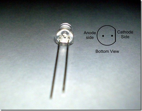
Hi guys, I'm putting together the kit I got from Tea-Bag and I'm little bit confused about the 5 LED group direction on the V- side of board, I know it was somewhere in this thread but can't find now...so which one is correct the imprint on board or the square hole showing the cathode?
all the best
Nicu
all the best
Nicu
LED Orientation from SALAS - Square hole is Led's anode in this pcb Positive Side is the Anode and has long wire
Also,
The LED should have a flat side on the underside... The flat side goes to the flat side imprinted on the board.
Keep us posted on the build. I'm about done collecting parts and plan to start soon myself
Also,
The LED should have a flat side on the underside... The flat side goes to the flat side imprinted on the board.
Keep us posted on the build. I'm about done collecting parts and plan to start soon myself
Last edited:
LED Orientation from SALAS - Square hole is Led's anode in this pcb Positive Side is the Anode and has long wire
Also,
The LED should have a flat side on the underside... The flat side goes to the flat side imprinted on the board.
Keep us posted on the build. I'm about done collecting parts and plan to start soon myself
mantha3 , thank you for reply,
in any case ,am I correct with this dirrection of LED's?
An externally hosted image should be here but it was not working when we last tested it.
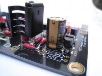
Here you see what I succeeded so farKeep us posted on the build. I'm about done collecting parts and plan to start soon myself
An externally hosted image should be here but it was not working when we last tested it.
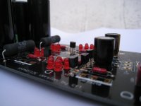
and buffer side
An externally hosted image should be here but it was not working when we last tested it.
I expect to complete with some Mundorfs AG 4700/40 capacitors and Takman resistors for buffer...
Looks great indeed!Nice work with the soldering iron. Looks great
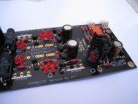
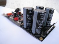
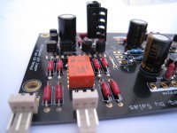
Here are some of my pics too while I'm at it. Please note that the jumpers are not yet installed. Neither are the FET's and the 0.22uF cap
The board is of good quality which make soldering a lot easier. Thanks for making it available!
Attachments
- Home
- Source & Line
- Analog Line Level
- Salas hotrodded blue DCB1 build