Thank you, Tea-Bag. I shall try that out soon.I measure voltage across the 2Sk's then run a test signal (can be a line source) into the input, and measure AC out voltage from the output. The voltage should be in the 9-10v range.
I forgot to mention, while i was testing the dcb1 i accidentally plugged out the right channel input while the CDP was still playing and there was a pretty nasty boom. Speakers still working, though i wonder if that killed the 2SKs/any other parts, which brings me to my next stupid question - is it always unsafe to unplug the rca in/out of the dcb1 while the amp and source is on?
RCA (phono) type connections have a basic fault.
The hot contacts first on insertion and disconnects last on extraction.
This is recipe for disaster with "ON/Live" equipment.
Most decent connectors make the ground first and Return next with Signal last. But even these should not normally be connected or disconnected "Live".
The hot contacts first on insertion and disconnects last on extraction.
This is recipe for disaster with "ON/Live" equipment.
Most decent connectors make the ground first and Return next with Signal last. But even these should not normally be connected or disconnected "Live".
Hi Tea-Bag,
Will there be any problem with in-rush if I use 4x 6800uF instead of the original 4x 4700uF ?
Not that I have experienced.
I have one that's 4x10,000uf for phono supply and no issues with fuses or components failures.
My second power amp had 4 off 4700uF as smoothing.
I changed to 12 off 6800uF for smoothing. That did not result in a fuse blowing problem.
The start up current of the 250VA transformer did cause a problem.
When mk3 came along the 625VA transformer needed a soft start, but the 80mF of smoothing still did not cause nuisance blowing.
There are two different problems. Start up current of the transformer and charging current of the smoothing.
The peaks of these two different short term loads do not coincide.
The soft start for the transformer is hardly needed after a few cycles of AC have passed through the primary winding.
While the transformer is "starting up" it cannot supply significant power/current to the smoothing. That peak charging current reaches it's maximum "after" the transformer has reaching operating condition.
Hmm, I tried this test and all 4 2SKs measure well in that range.I measure voltage across the 2Sk's then run a test signal (can be a line source) into the input, and measure AC out voltage from the output. The voltage should be in the 9-10v range.
Salas, would you care to elaborate more specifically on what i'm supposed to doing? Using DVM with ACV of setting 200, I fed 300Hz, probed the live and ground, input gave me 3, volume pot as well, but no readings on the dcb1 outputs ... ?Some discharge when you were handling the boards maybe, can't say. You need to feed signal and follow it, to see where it stops. If you don't have an oscope, DVM on ACV can detect. Feed 300Hz (test CD, or there are software generators free, google up) at about 1VRMS and see until where it makes it by probing the path, starting from input RCA, finishing at output RCA including interconnect cables. With DVM on Ohm you can check continuity, if relay engages, etc. 100% audio circuit jfet matching helps offset naturally.
I tried googling more on how ACV works but still confused on what it really does.
While feeding the test signal, i also tried measuring DC (set to 200 mv). There were values at the input and output.
Any further help is greatly appreciated!
Set it at 20V range. Do you trace up to the 1V AC (or 3?) that you feed it as you turn up the DCB1's volume pot, going to the pot, exiting it, on the input 220R, on the Jfets, on the output 220R, on the relay, on the relay output, does it stop reading somewhere? Where exactly? That should be the problem connection or part.
Hmm, there is AC from pot, exiting pot, but nothing on the two input and output 220Rs. Nothing on jfets if i measure AC, but there is 9.50+ DC on them. Not sure which pins of the relay i should be probing... i checked the datasheet but i don't see where they mentioned that bit of infoSet it at 20V range. Do you trace up to the 1V AC (or 3?) that you feed it as you turn up the DCB1's volume pot, going to the pot, exiting it, on the input 220R, on the Jfets, on the output 220R, on the relay, on the relay output, does it stop reading somewhere? Where exactly? That should be the problem connection or part.
That result fixes attention to the route portion from board signal input pins to input 220R. Do you use connectors to the board? Check there is connection continuity. You should be probing for signal the pins connected to the 220R resistors. There should also be -9.5VDC or about there to the other side.
Okay.. this is real odd.DC on drain of one fet +V. DC on source of other fet -V. AC after pot continuing to 220R to gate of the +V fet, AC exiting to the other 220R between the two fets, AC on the output of engaged relay to RCA out.
DC on fets - yes
AC after pot - yes
AC exiting 220R - no reading; AC reads as 0. I thought i was not probing it properly but it was connected properly.
I took out all the resistors and relay. Bought extra resistors the first time round and have an extra relay on hand, so might as well give it a go... fingers crossed it works
Okay.. now i'm completely clueless.
I replaced the relay and all the resistors in the input and output section. Still the same problem, right channel with very very little volume and left channel 100% functioning. Fets measure fine too. RCA sockets have good solder connections. Unless it's possible for a RCA socket to spoil... ?
Anything else i should be trying?
I'm really just guessing here, but I've seen similar symptoms ("very very little volume") in other devices in case of a short circuit between signal and ground.
I'm really just guessing here, but I've seen similar symptoms ("very very little volume") in other devices in case of a short circuit between signal and ground.
I've had a similiar issue, but it was amplifier speaker out hitting chassis ground.
*If someone is perfectionist about matching the Verf LED gangs of 5, the best maniac party trick is to use a *12V battery, connect gate and source together in the specific 2SK170s that are going to feed those strings (those Jfets above 1R), feed (+) to the drain, connect g&s node to LEDS string, return string's other end to (-), and swap between enough glow bugs until you got 2 total across 5 LEDS Voltage matches, each to its own Jfet. For the cherry on the cake set DVM that measures diode drop (some got it) and find 2 Vbe matched BC550 & 560.
Practical benefit? Next to nothing. Aesthetic ritualistic benefit? Priceless.
*9V,1.5V,1.5V batteries in series that are common types, maybe already in remote controls on the coffee table, will do for 12V total. And don't post pics from the parking space tapping on the car's stuff.")
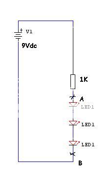
Hi Salas,
Can I measure point A and B for Vf on the LED string for getting 2 sets of 3 LED strings with the closest value?
Okay.. i replaced the RCA socket and still not working.Okay.. now i'm completely clueless.
I replaced the relay and all the resistors in the input and output section. Still the same problem, right channel with very very little volume and left channel 100% functioning. Fets measure fine too. RCA sockets have good solder connections. Unless it's possible for a RCA socket to spoil... ?
Anything else i should be trying?
Does anyone have any more suggestions pretty please? I'm at my wit's end...
- Home
- Source & Line
- Analog Line Level
- Salas hotrodded blue DCB1 build