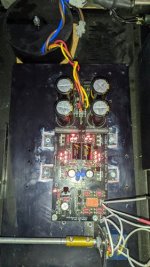
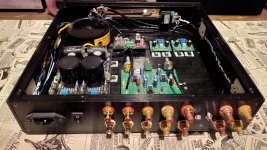
I mounted the 1 ohm resistors
So, lots of current available. It's a 10W resistor (Mills ?), I bet it's getting quite hot. I use Caddocks and when I drop from 8 Ohm to 1.5 Ohm I opted for a heatsink (not only for the resistors but also for rectifiers too). Without doing any serious comparison I was amazed by the improvement. Time passed and now I decided to a A-B comparison between the two and see if the overall heat management needed is justifiable.
Therefore I put them on mini-pcbs so I can quickly swap them. I secretly wish that it wouldn't make so much different 'cause heat dissipation is such a problem for chassis building.
Why such a huge current headroom makes a different escapes me and I was in denial till I've tried it.
Hi Savvas,
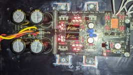
as said I had the dcb1 in the drawer, because compared to the aleph 1.7 with the 5 ohm resistors it was not very dynamic.
the other morning I change the resistors using 1 ohm DALE.
Since the first assembly of Salas' dcb1 I had already mounted an oversized heatsink (25X15X3 cm) just for this type of configuration.
"Without making any serious comparison, I was amazed by the improvement"
This sentence of yours I agree to 200% and now the difference compared to the aleph 1.7, set however with the gain at the minimum of the three possible values, is not very marked or completely non-existent.
Now the low frequency control has improved considerably
One question, which of you thinks the sound is a little amber? dark?
I'm not saying not very detailed but if anything not very bright in the highs?
Attachments
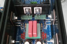
So far In comparison with DCG3, DCB1 is more forward sounding, missing in HF and LF extension. The word I was thinking was 'tubey' when I heard it with Wima MKP4 in the filtering (voltage reference), someone else might as well say dark' too.
Changing to Wima MKP10 made a difference, gone the 'tubey' sound, more air and details in soundstage, more in the direction of DCG3's character, let's say halfway. It's still has more 2-dimentional presentation but more musical and 'meatier' sound but without the huge soundstage and details of DCG3 which also is little bit more dynamic.
Both have the same volume attenuator (Muses) / selector (I-Select) / cables and connectors
Still evaluating, doing a more proper A-B comparison
Attachments
Thanks Nick. I don't expect night-and-day differences since I've already got Dale 0.1% resistors there but you never know.
It's funny that I never thought that I would give that much attention to DCB1, I only did it because I had the board available and some parts handy.
As always, with good circuits, I find somethings I do love and somethings I don't. Changing parts could make a difference and a small compromise could be made otherwise we are in for a fast-as-lightning divorce. Let me see...
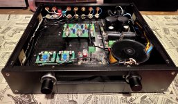
another modification on my DCB1 with BiB supply. 2 input & 4 output
input selector from DAC & AVR (front only), additional selector for subwoofer from AVR LFE
output from DCB1 goes to Selector 4 output and subwoofer controller to feed behringer nu3000dsp for my dual-opposed subwoofer. this sub-out has a selector to get it from subwoofer controller or AVR LFE
4 output from manual selector :
1. direct from dcb1 to rca, this is used for my amplifier with high gain like J2 clone or Gainclone. prepared for Elsinore speaker
2. to amb a20 with 15dB gain, good option for low gain amplifier like SIT L'Amp or M2 clone. currently powering AudioNirvana Classic 8
3. to minidsp 2x4HD that feed into my 2 way OB
4. to LXmini kit which is prepared for future OB build
previously i have to plug-unplug my rca cables because only 1 output available, now it's nice to have multiple output that drive different set of amplifier & speaker
Attachments
Dear fellow DCB1 enthusiasts,
Because I am an idiot, I've made a mistake ordering my custom Toroidy transformer. It is a work of art but it has 2x 15V secondaries where I needed/wanted 15-0-15V for the DCB1. I read that 20V is max for the DCB1. Is this correct? Could someone with more electronic wisdom than I help me? Can I still use this? Wiring the 2 15 secondaries as a centertap would give me 30V if not mistaking. This seems like a way to toast the DCB1. I hope that there is a (simple) fix. If not I probably need to get another transformer made or find myself another buffer option. I'd rather not spend the money on another transformer though.
Because I am an idiot, I've made a mistake ordering my custom Toroidy transformer. It is a work of art but it has 2x 15V secondaries where I needed/wanted 15-0-15V for the DCB1. I read that 20V is max for the DCB1. Is this correct? Could someone with more electronic wisdom than I help me? Can I still use this? Wiring the 2 15 secondaries as a centertap would give me 30V if not mistaking. This seems like a way to toast the DCB1. I hope that there is a (simple) fix. If not I probably need to get another transformer made or find myself another buffer option. I'd rather not spend the money on another transformer though.
Twist one wire from each secondary together, no matter which. Turn on and measure voltage between the two open ends. If you get ¨30VAC then you have a 15-0-15 transformer. If you get close to 0V switch the wires on one secondary only and measure again. Now you shuld have 30VAC.Dear fellow DCB1 enthusiasts,
Because I am an idiot, I've made a mistake ordering my custom Toroidy transformer. It is a work of art but it has 2x 15V secondaries where I needed/wanted 15-0-15V for the DCB1. I read that 20V is max for the DCB1. Is this correct? Could someone with more electronic wisdom than I help me? Can I still use this? Wiring the 2 15 secondaries as a centertap would give me 30V if not mistaking. This seems like a way to toast the DCB1. I hope that there is a (simple) fix. If not I probably need to get another transformer made or find myself another buffer option. I'd rather not spend the money on another transformer though.
First is to know the correct wiring by colors from a label or from a datasheet. If without that info, can also ask with an email to the manufacturer.
When finding out experimentally and seeing close to zero AC secondaries must also act swiftly because the transformer may heat up fast due to the secondaries are wired out of phase with each other.
When finding out experimentally and seeing close to zero AC secondaries must also act swiftly because the transformer may heat up fast due to the secondaries are wired out of phase with each other.
So attaching the correct ends together an connecting to the 0V/center tap position on the board and the other ends to the 15V position is just fine and the fact that the combined voltage would be 30V is good? That would be a major relief. I have all the data of the built transformer so wiring it correctly is not a problem. Toroidy has a great product and service.DCB1 uses +/- supplies set around a center tap so your transformer is alright to create that.
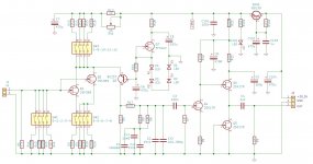
Salas, I am contemplating building the UFSP. Made the schematic and a take on a single sided PCB. But maybe I will go for 2-layer...
I have tried to follow your schematic as good as I can, but could you give it a glance to see if something is terribly wrong? Thanks!
Then about ground plane: is it to avoid on the project, or will it be a benefit?
Edit: Sorry, this came in the wrong thread!
I have tried to follow your schematic as good as I can, but could you give it a glance to see if something is terribly wrong? Thanks!
Then about ground plane: is it to avoid on the project, or will it be a benefit?
Edit: Sorry, this came in the wrong thread!
Attachments
- Home
- Source & Line
- Analog Line Level
- Salas hotrodded blue DCB1 build