
I have two questions then:
There is an added green trace between the 220R and AGND in version 2. In version one, the output from the jfets is connected to either the output pin or is left floating.
In version two, the output from the jfets is connected to the output pin when the power is either on or off, and is also connected to ground when the power is off, effectively shorting the input to the power amp.
Is this why you can turn off the DCB1 before the amp?
2) In the shunt schematics, the grounds are not labelled AGND. The buffer and relay grounds are labelled AGND.
Is the intent for the second ground termination (AGND?) nearest the jfets to be separated from the Shunt ground with a ground loop isolator?
Then is it correct if the shunt grounds go directly to the Power supply center tap (Zero volt line) and safety earth, while the AGND passes through a ground loop isolator then to the zero volt line....
Is the 1M resistor necessary?
When the unit is off and jfets out, I measure 0 ohm with probes on either side of the 1M resistor. That corresponds to the second drawing.
Why I moved the resting off position of the output relay to ground back then was because a high impedance high gain power amp was reported picking some interference over the interconnection if it was on while the DCB1 was off. To prevent more cases. The DCB1 project was so popular I had to think about odd scenarios.
I am at a loss on how many Hypnos and Mezes have been put together in eleven years but in their fresh period the builds were coming in waves.
Although the relay disengages its output signal contact fast to ground when turned off, its still good practice to traditionally turn power amp on last / off first. Disengaging relay contacts can still pop some medium intensity noise.
The relay's missions are: a) Delay output during power on for a short moment allowing DCB1 to stabilize for DC offset b) Disengage fast at power off before a large DC offset cycle starts forming due to unevenly draining supplies.
AGND was just some lane marking in the CAD not representing an alternative ground scheme. In the board file its stamped all over ground traces in the PSU section too. Along with +10V -10V rail marks etc. None of those marks was meant to be used for copper etching.
The 1M output resistor is not strictly necessary. It just keeps a tight loop local ground reference no matter what may happen at the other ground end of the output interconnect.
THANK YOU!
I really appreciate the insight! Not to mention all the help. Wow, thanks again.
I have one last query.... it is about J2. J2 is in such a position that it appears it could be replaced with a 1-2 ohm "hum breaking" resistor similar to what people add in the F5T to lift the front end section ground from the noisy zero volt line. ( in the F5T, I added a 2 ohm resistor and dropped the hum about -15dB ) Would doing this here *further* decrease power supply noise?
I have yet to add mica/ceramic caps from RCA input shield to case ground. Similarly for transfomer snubbers..... With such stellar performance, I am not sure they are needed either.
Because of the very good noise performance with the board as is I am not aware of any reported builds that ever attempted hum breaking at J2(Jumper2). That is why a copper lane got eventually established under the J2 white line later on when the boards went double sided. If you will measure without a wire link installed you will find there is still continuity for that J2 white line. Same is true for J1.
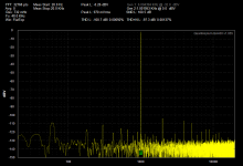
Ha, very comparable to your analyzer's own loopback. Looks like you did a good build job. Doesn't seem to add anything significant of its own.
For even better results and a more trustworthy baseline try to improve your analyzer's loopback. Maybe with shorter better shielded cables. Their ground side especially must be gripping well.
If no success, also see what happens if moving the analyzer away from potential interference sources while its running own loopback. First unplug one by one usual offenders like a home network router, SMPS wall warts, computers, Led lighting etc.
It's very difficult in this room. There are pot lights everywhere, there is a water meter with transmitter a few feet away..... At this level, putting it into a metal pot might be advisable.
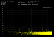
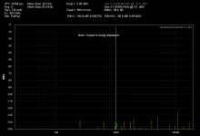
You can tell there is something going on with the DCB1, as the volume is slightly lower, and the third is showing lower. I assume that is of different polarity than the third on the analyzer. As you change the volume, the chart changes a lot, so I know it's hooked up right. Those shots are at full output.
This build has a potted transformer, which is in the enclosure along with the rca jacks and volume control. The board is on the outside of the enclosure, along with the heatsinks. So the board is isolated from the transformer somewhat.... I did drill some holes in the enclosure for air to flow from below the board, and keep the transformer temp down.
It's very difficult in this room. There are pot lights everywhere, there is a water meter with transmitter a few feet away..... At this level, putting it into a metal pot might be advisable.
You can tell there is something going on with the DCB1, as the volume is slightly lower, and the third is showing lower. I assume that is of different polarity than the third on the analyzer. As you change the volume, the chart changes a lot, so I know it's hooked up right. Those shots are at full output.
This build has a potted transformer, which is in the enclosure along with the rca jacks and volume control. The board is on the outside of the enclosure, along with the heatsinks. So the board is isolated from the transformer somewhat.... I did drill some holes in the enclosure for air to flow from below the board, and keep the transformer temp down.
Yes, real voltage buffer circuits aren't 100% times one. They are approximately unity. Infinite input impedance and zero output impedance are ideals. In this case able to pass 97% of input voltage level. Maybe joints and contacts in a build contribute some little part of that -3% loss too.
About your QA400 analyzer's harmonic noise baseline and possible susceptibility to low level interference, how long are your test cables? Also why you prefer Flat Top window setting and not the more usual Hanning? Why not choosing more analysis points than 32k?
About your QA400 analyzer's harmonic noise baseline and possible susceptibility to low level interference, how long are your test cables? Also why you prefer Flat Top window setting and not the more usual Hanning? Why not choosing more analysis points than 32k?
Why not? Because I don't know so much about test equipment.
The test cables are very long.... probably 10 feet. They are twisted tightly together though I think I have some shorter ones. Will have a look.
More points, ok, I'll do that.
I read in the QA manual that Flat top was better for amplitude measurement.
Hi Salas,
I tested my Balanced hotrod DCB1 with SE input/output last time without problem. It sounds excellent.
When I tried balanced, the left channel XLR is very quiet like 1/5 Volume level of the right channel. Very little hum is present.
Would it be the wiring? Or the negative side somewhere is problematic?
Where can I start to troubleshoot?
( my newly built M2 also has the left channel problem Similar to this but I did not test them together so they should be two separate issues; I tested my other diy integrated amp and it works fine )
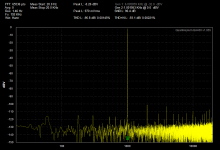
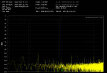
Lower main hum spikes for the DCB1 chart to the left. Still QA400 loopback picks interference from somewhere around the bench but the harmonic noise levels are low enough to know your DCB1 ain't adding some extra. Not a squeaky clean analyzer baseline to reliably characterize quiet DUTs but good enough to know if they are a practical pass for your purposes.
THANKS.
I was just looking for something that might tell me where there may be potential problems. This exercise showed that the big 60hz bubble is the analyzer.
I wonder what REW might show, but then the cables would not be so well shielded. I might have cheap RCA to TRS. Maybe making my own would be better?
- Home
- Source & Line
- Analog Line Level
- Salas hotrodded blue DCB1 build