Hi All,
So just to finalize my thought
the Dual secondaries for Center Tap input should be like shown above.
I will measure the hot wires with the light bulb tester to make sure I am using the correct secondaries and won't be getting 30V instead of dual 15
Thanks for your help !
So just to finalize my thought
An externally hosted image should be here but it was not working when we last tested it.
the Dual secondaries for Center Tap input should be like shown above.
I will measure the hot wires with the light bulb tester to make sure I am using the correct secondaries and won't be getting 30V instead of dual 15
Thanks for your help !
measure three voltages.
V'= ?
V" = ?
2V = ?
V"+V' should equal 2V.
once you have that conformed, you can add on the rectifier and smoothing caps.
Then check the three DC voltages.
If this is correct, then power OFF and discharge the capacitors slowly. Use a resistor not a screwdriver.
But the DCB1 does not allow you to sequentially add the various components unless you assemble it to allow sequential testing.
Ok have verified the Trafos.
12v one is giving 13.8 which actually looks closed to the suggested value of 13v
15v output is giving 17,4 secondaries. In center tapped mode.
The V total is 34,8 quite good.
Will be measuring the offset now.
Thanks for all the feedback)
Sent from my ONE A2003 using Tapatalk
12v one is giving 13.8 which actually looks closed to the suggested value of 13v
15v output is giving 17,4 secondaries. In center tapped mode.
The V total is 34,8 quite good.
Will be measuring the offset now.
Thanks for all the feedback)
Sent from my ONE A2003 using Tapatalk
Attachments
Last edited:
All lights are on. Alright, good start.  Are those AC figures measured when the transformers are loaded (connected to dcb1)? Or its about the DC rectified you get? BTW you can measure raw DC on points at the top of the board also, not only at the pins of the big filter capacitors underneath.
Are those AC figures measured when the transformers are loaded (connected to dcb1)? Or its about the DC rectified you get? BTW you can measure raw DC on points at the top of the board also, not only at the pins of the big filter capacitors underneath.Attachments
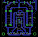
converting a Dual secondary to a centre tapped secondary
Build a Mains Bulb Tester.
Use it to prevent damage to your transformer.
Then check your output voltages BEFORE you connect them to a PSU.
Go Back to Post5151 and read on from there.
I thought you understood that.
What is your new question?
Be careful. Wiring the secondaries incorrectly can blow up your amp and/or damage your transformer.Was not sure how to make a center tap output from a dual output Trafo.
Build a Mains Bulb Tester.
Use it to prevent damage to your transformer.
Then check your output voltages BEFORE you connect them to a PSU.
Go Back to Post5151 and read on from there.
I thought you understood that.
What is your new question?
Last edited:
Decoupling Caps A and B
Hi everyone. Thanks for the help with my last query. Question: I have the Mezmerize Salas DCB 1 V1.0 blue board and it is almost all populated.
However, I can't seem to find the spot for the decoupling A 150nf cap. I placed the 100nf Decoupling B cap by the 7812 already. The BOM lists the spot for the 150nf cap near the C517.
Am I blind? Do I have a board revision that dropped this component? Thanks!
-Corey
Its only optional if any mechanical chatter occurs in the relay. It goes directly across base and collector pins at the bottom layer. If someone can't get a BC517 Darlington and must use a BC550 etc. which does not have the enormous current gain, it is possible to get a resonance between the driver transistor and the relay's coil inductance. That capacitor solves it.
Its only optional if any mechanical chatter occurs in the relay. It goes directly across base and collector pins at the bottom layer. If someone can't get a BC517 Darlington and must use a BC550 etc. which does not have the enormous current gain, it is possible to get a resonance between the driver transistor and the relay's coil inductance. That capacitor solves it.
Thank you once again Salas. Very excited to power it up. Just waiting on my anodized purple chassis. Prince would be proud.
Good luck and let us knowAn externally hosted image should be here but it was not working when we last tested it.
CCS lower than expected
Salas--Classic prince. Nicely done.
I am an idiot and posted the following in the diyaudio store forum. Sorry...
Hi all. One more for today. I attempted a forum search and I'm sure this has been answered before but I'm afraid I can't find it.
Powered up my Hot Rod Mezmerize DCB1 today and I'm afraid the CCS is running quite a bit lower than what I would expect.
Measurements as follows:
LED's all matched at 1.9Vf
Bank of 3= 5.7v
Bank of 5=9.5v
R1=single 7w 3r3 ohm resistor per side
+Rail tests at 10.59vdc
-Rail tests at -10.13
Vdrop across R1
+ Rail=1.54v
- Rail=1.52v
With my resistor, that puts me at ~465mA vs expected 600mA
I think it should be closer to 2v on the vdrop. Is it because my Vf is a little high?
Also, my power transformer is an EI, 14-0-14 rated to 4amps but it runs warm. After 30 minutes on, it's running about 20 degrees C above ambient. Maybe that's fine, but I don't know enough to know if this is okay or maybe related to the reason my Vdrop is low.
Anything else needed to diagnose and fix the problem? Thanks everyone.
Corey
What is the Vdc at the smoothing caps?
What is the Vdrop from smoothing caps to regulated rails?
At lowest mains voltage this needs to be higher than ~ 4V to 5Vdrop.
This requires that the Vdrop for normal mains voltage should be ~7Vdrop.
I had a look at post1 sch and found R1. It is an audio signal resistor connected to the signal transistor T1.
What sch are you using?
Last edited:
Corey
Your build responds normally. You would need green LEDS in the triplets with your particular MOSFET batch VGS in order to go nearer 2V Rdrop=VFtot-VGS but with your transformer being already warm I would suggest you stick with your now current level which is plenty anyway. And your resistors save some self heat. Your EI has less power efficiency than a donut but its a better mains filter and tolerates little DC component in distorted mains. 20C above ambient should be safe for an EI in long term use.
* I moved those two posts here for coherency
Hi Andrew thank you and I think it is all right.
I have double checked the series connections of secondaries on both Trafos and they are behaving like center tapped.
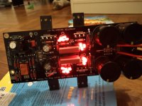
Measured the DC on the power output of the dcb1 today with no signal and no load. Photos attached I am getting +9.65 and -9.75
Should I check the output signal without load?


I have double checked the series connections of secondaries on both Trafos and they are behaving like center tapped.
Measured the DC on the power output of the dcb1 today with no signal and no load. Photos attached I am getting +9.65 and -9.75
Should I check the output signal without load?
Last edited:
The raw supply is actually loaded by the four JFETS draw and the much higher CCS current that its shunted to ground. The signal swing will only make a very small difference to that state. That's the idea and a big contribution to the dcb1's performance. What is the rectified DC with what transformer at the points I showed you on the rectification side of the board? You can measure you DC offset at the signal outputs without anything else connected, as well as the voltage drop on the current setting resistors to derive the CCS current. If both are acceptable and the raw DC rectified level is 15V or more you are ready.
- Home
- Source & Line
- Analog Line Level
- Salas hotrodded blue DCB1 build