Regarding the Antek 50 VA transformer, how should the purple wire "static shield " be handled?
Goes to chassis earth on a lug in a short manner. Chassis should be mains earth connected near the IEC inlet on some lug also. Some take the static shield cable to the same mains earth lug too if the transformer is near anyway. In general, the shortest the purple path to chassis is, the less its inductance the better the RFI grounding.
Hi,
I've just started building my DCB1 Hypnotize kit and have a couple of stupid questions that I would be grateful if someone could answer. I've read as much as I can of this and the other Mez monster threads but can't find the answers I need (or answers written in a language a newby can understand).
-I'm going to hot-rod. Starting with 10ohm then working my way up. I've seen various heatsinks with various values/modifications to the design but can't see anyone stating a required size or dissipation value. At the max hot rod setting what sort of size sink am I looking for; presumably bolting to the case won't cut when hot-rodded to this level? Shipping of cases is quite expensive to the UK so I just want to ensure it integrates properly. Something like this if one per FET
07WN-01500-A-200 - H S MARSTON - HEAT SINK, UNDRILLED, 1.5°C/W | Farnell UK
or am I better buying large sinks and using them as the walls to the chassis, like a class A amp?
-The build guide suggests that for a hot rod you may want consider a transformer of 2x15v 50-100VA. Most builds I have seen here have different values (even if hot rodded) for the secondarys and VA rating. How critical is it to get these values correct? The price difference between a 50VA and a 100VA transformer is negligible so if I understand VA ratings properly I should just go for 100VA just in case I want to use it for more demanding uses in the future?
-When I understand things a bit better I aspire to have a remote controlled volume and input selector. Is the Vout point on the board suitable for powering these additions if combined with an appropriate regulator?
Thanks in advance, I'm sure I'll be back with more later.
-Power dissipation on each MOSFET in Watt is the product of voltage across it and current through it. Expect 10V on each when using a 15+15V AC transformer. Calculate for your chosen hot rod current value. i.e. If you decide 1 Ampere you will have 10W per MOSFET 20W per rail 40W total. Say with 1C/W spec sink common between two MOSFETs per side will theoretically rise 20C above ambient. Isolate the MOSFETS backs to the sinks with Silpads. Derate by 30%. That makes for 26C above ambient. Don't run on more than 60C combined in general so its rather safe to handle. Use that logic to choose any sink individual or common between one or two MOSFETs for any hot rod level in any room ambient temperature conditions expected.
-Get 100W since you will hot rod, its not that much bigger or expensive anyway. Has less impedance, even if you will not push its delivery in the future, can't be a bad thing.
-Although it could power some extras I would suggest not to mix other devices unless you can measure they aren't introducing interference. Its a sensitive node that the audio circuit sees directly for its power drain.
Use that logic to choose any sink individual or common between one or two MOSFETs for any hot rod level in any room ambient temperature conditions expected.
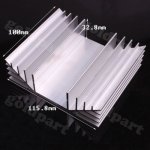
Salas, I bought this heat sink on eBay just using a dumb "that looks beefy enough" approach; it's from China with no real specs except the dimensions. My plan is to bolt cut in lengthwise down the middle and bolt two transistors to each resulting half, as well as down through the bottom plate of my case, which will be large and is a perforated 1mm aluminum sheet. The case will be well ventilated.
If I'm running 600 mA, do you have any gut feeling about whether I will have adequate cooling? Thanks.
Attachments
And here I am with some more.Thanks in advance, I'm sure I'll be back with more later.
Thanks Salas for your reply.
When powering a remote input/volume unit how would recommend doing it to minimise possible interface without using a separate transformer? Using a regulator prior to DCB1 board to tap off 5V/12V? for example as Mooly explains here:
http://www.diyaudio.com/forums/power-supplies/250434-newbie-power-question.html
The idea of a remote capability is someway off, in the mean time I'm just going to use a manual pot and selector. At the risk of sounding an idiot what is the Vout for?
Cheers
Salas, I bought this heat sink on eBay just using a dumb "that looks beefy enough" approach; it's from China with no real specs except the dimensions. My plan is to bolt cut in lengthwise down the middle and bolt two transistors to each resulting half, as well as down through the bottom plate of my case, which will be large and is a perforated 1mm aluminum sheet. The case will be well ventilated.
If I'm running 600 mA, do you have any gut feeling about whether I will have adequate cooling? Thanks.
I don't think you will have excessive heat with those. Get a cheap K thermocouple temperature probe from eBay or somewhere too so you can monitor your results. Just 100mA less can make a good difference if some thermal scheme is on the edge of becoming uncomfortably hot.
The MOSFETs are quite tough themselves but too high sink and case temperature makes a build problematically hot to operate and touch plus it creates a baking pan for the rest of its components shortening their lifetime.
It's mentioned somewhere in one of these threads, but I think the VOut is meant to let you access the board's power supply for ... whatever it may be suited for; it's just a generic power source.
It was actually meant for those planning to use a DCB1 as dedicated power regulator for other gear, with its audio section unpopulated or cut off.
And here I am with some more.
Thanks Salas for your reply.
When powering a remote input/volume unit how would recommend doing it to minimise possible interface without using a separate transformer? U
Cheers
Tapping off from the main filter capacitors to a dedicated linear chip regulator for support circuits.
Thanks for all the information, Salas!
Anima999, I meant to mention also that I will be using a Goldpoint Mini-V stepped attenuator with my build, and a Bent Audio remote control module / motor to drive the volume control remotely. It comes with an optional lovely metal remote control. I bought a 12VDC cheap power supply on eBay (maybe $6?) to power the remote control motor and in testing, it seems fine. I have a thread going here if you're interested:
Pass/Salas DCB1 Preamp Layout Questions - Page 3 - AudioKarma.org Home Audio Stereo Discussion Forums
ZIt looks like we are trying to achieve the same thing except I was hoping to power everything off of one transformer and the Goldpoint and Bent audio stuff is a bit out of my price range.
I can't measure any interference so I might just plug it in and see what happens.
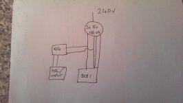
I've attached a very tough sketch of what I'm suggesting.
I can't measure any interference so I might just plug it in and see what happens.
I've attached a very tough sketch of what I'm suggesting.
Attachments
Last edited:
-Power dissipation on each MOSFET in Watt is the product of voltage across it and current through it. Expect 10V on each when using a 15+15V AC transformer. Calculate for your chosen hot rod current value. i.e. If you decide 1 Ampere you will have 10W per MOSFET 20W per rail 40W total. Say with 1C/W spec sink common between two MOSFETs per side will theoretically rise 20C above ambient. Isolate the MOSFETS backs to the sinks with Silpads. Derate by 30%. That makes for 26C above ambient. Don't run on more than 60C combined in general so its rather safe to handle. Use that logic to choose any sink individual or common between one or two MOSFETs for any hot rod level in any room ambient temperature conditions expected.
Just so I understand your last sentence what do you mean by "60C combined"? 60C for the two MOSFETS on the rail when they are combined on the same sink - 60C one side and 60C the other? Or do you mean 60C for all 4 MOSFETS combined - 30C one side and 30C the other?
Assuming you meant the first - 60C per heatsink. Working backwards:
1 Amp hot rod. Ambient temp of around 20C.
60C max temp - 20C ambient = 40C max rise
40C = 20W x 1.5 + 30%
The heatsink needs to be of at least 1.5C/W
If I chose individual sinks then it needs to be at least 3C/W
Is this the right tree to be barking up?
I'm in England...20C is optimistic for most of the year.
Simplifies the max demand thermal engineering allowance.
")
Hi again!
I have a question regarding setting the current of the regulator. I am using a CRC pre-regulator with nominal 10 ohm cement block resistors.
Here are the data points:
Negative rail:
Resistor: 2.5 ohms.
Prereg out: -20.7 V
Reg in: -19.4 V
Reg out: -10.27 V
Reg DeltaV: 9.13
Positive Rail
Resistor: 3 ohms.
Prereg out: 20 V
Reg in: 17.95 V
Reg out: 10.25 V
Reg DeltaV: 7.7V
How can I get the positive an negative regulators to draw the same current?
Thank you!
- Home
- Source & Line
- Analog Line Level
- Salas hotrodded blue DCB1 build