Nice build, congrads ! Do you have a photo of how you fit everything inside?")
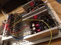
Will not be able to take a photo of the final look,but here for the reference:
In addition:
Small eBay regulator board for the controller goes to the front left between faceplate and the trafo.
Attenuator and selector switch goes to the rear right behind the pre board.
Also it has DCSTB not BIB.

My third DCG3, thank you Salas!
View attachment 740663
Very nice !
Where did you get your volume control and display?
Fab
Salas, could you explain in detail the ground wiring procedure? I have mains earth to chassis and I read that I need to add signal ground to chassis as well via resistor. Is it best to connect all input/output signal ground into single wire and ground to chassis or any other way is preferable?
Having the chassis referenced at same "zero" potential as the pre-amp's is good against EMI & RFI. But don't connect signal ground wires to that chassis cable. There is a ground lane running across the front of the pre-amp that has all those already connected together. Just run a wire from one HP G pad to the chassis.
There are also a couple of blind rectangular ground pads at the bottom layer of the PCB's front edge reserved for various grounding schemes wiring to look neater. Those are HP G extensions. The outer ones, because there are two extra blind pads towards the center too. Don't use them by mistake, those to the center carry line output signal.
In the newest board there are just two L looking blind ground pads near its center front at the bottom layer. Those can be used to bridge the channels grounds if there is hum when separate as they come or to run a cable to chassis as well.
You may also introduce an NTC thermistor between chassis lug and the PCB to chassis cable for potential ground loop breaking purposes within the audio system.
So it has some elevated resistance when cool but in case of a an accident that will look to run fault current from the pre-amp to the mains earth through the chassis it warms up and its resistance diminishes.
Some NTC part for inrush current limiting applications like the EPCOS B57364S0100M000 will do the job.

Need some help troubleshooting.. I have re-arranged some stuff in the build and fired up again. One of the negative UBibs show no voltage across (the lights are off) when connected to the DCG3. Otherwise disconnected all is fine. Any idea what could've damaged in between and what to check first?
So... Got 2 toroids with 50va... Now I just need another two for balanced...
Good luck with your forthcoming build
@trancendent
Sounds like after the rearrangements you somehow short that PSU's output and its current limiter kicks in. See if it's about you had burned the DN Mosfet on that negative rail or an insulation has been compromised or you simply miswired something.
Thanks Salas. Here's short update after quick test. Didn't have much time to investigate in detail yet.
Connected PSU to DCG3. Shorted the inputs on DCG3 and connected the output wires - the PSU lights go on when fired on. I did remove the HP G wire to chassis though.
Could this indicate wiring issue on inputs? I have tested Mosfet insulation - no errors.
So... Got 2 toroids with 50va... Now I just need another two for balanced...
So it's two DCSTB or 8 UBIBs, right ? I don't know if anyone done that. Anyway good luck and do tell us your opinion when you finally have done it
First determine if its a channel issue or a PSU issue. Exchange channels to PSUs.
False alarm. It was insulation issue on failed PSU. I should really tripple check that all the time. Thanks anyways
Heh, saved me some time and money I guess..
Anyways, testing new heatsinks.. playing for an hour now. Both positive regs gets quite hot, but easily touchable. Negative ones barely warm. Kitchen thermometer goes up to 44C, but knowing the quality I'd add up couple more Doesn't sound too bad in any case..
Anyways, testing new heatsinks.. playing for an hour now. Both positive regs gets quite hot, but easily touchable. Negative ones barely warm. Kitchen thermometer goes up to 44C, but knowing the quality I'd add up couple more
Doesn't sound too bad in any case..Attachments
- Home
- Source & Line
- Analog Line Level
- Salas DCG3 preamp (line & headphone)