Regarding taking auxiliary power from the DCSTB or C2, I finally opted for the DCSTB. I had no issues running from C2, until I attached the VU meters. With the VU meters board there was a constant noise when powering from C2. No obvious ground loop there. Switched to DCSTB output and the noise was gone. I was providing the signal to the VU meters board from the headphones socket.Better not borrow from your DCSTB 17.6V regulated output. Not to mix a potentially interference prone line.
At underside DCSTB 2200uF C2's pins you will find +V/0V raw DC points to tap. Will almost certainly measure higher than 24V given your mains & transformers.
Put a 10k resistor in series with the switch's red or black thinner wire feed to its LED so to protect it.
Or a 20k trimmer wired like a rheostat (adjustable series resistor) to can control your preferred brightness. Start from midpoint trimmer setting before power on.
You also have an I-Selector input relays board which has an +12VDC regulated provision option from its LM7812.
Either the C2 voltage was too high or too raw (ripple) for your VU meter or a ground loop was forming between signal ground from the HP socket and the power ground from C2 through the VU. Anyway, you found a well working solution already.
Either the C2 voltage was too high or too raw (ripple) for your VU meter or a ground loop was forming between signal ground from the HP socket and the power ground from C2 through the VU. Anyway, you found a well working solution already.
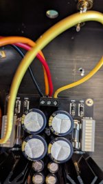
My DCG3 is finally complete. Here some photos of the last stages and final completion and a few comments. With the lid closed, I get 54-55C inside the heat sink, when having the amplifier on the top shelf. I like the outcome a lot. Using it now with AT M50x and Truthear Zero reds for headphones. In the main system I use it with a Trends Audio P10 or (P10.1), I don't remember which one it is. It sounds really good, not as full as the Unison Research S8 (845 tube amp), but really good and in plenty ways better than the tube amp. I may try another power amp in the near future. I am thinking of giving a try to purifi. Any suggestions are welcome. A big thank you for the support and especially to @Salas for offering his designs to the community. Now my system is quite Salas-ized (DCG3 with I-Select and UFSP) ")


C2 was feeding the I-select and then everything else (remote control board and vu meter board) from the I-select dc out.You also have an I-Selector input relays board which has an +12VDC regulated provision option from its LM7812.
Either the C2 voltage was too high or too raw (ripple) for your VU meter or a ground loop was forming between signal ground from the HP socket and the power ground from C2 through the VU. Anyway, you found a well working solution already.
Aha, that is why another path was formed when with the VU. Because both I-Select and VU employed the signal ground.C2 was feeding the I-select and then everything else (remote control board and vu meter board) from the I-select dc out.
If yours is a single input only configuration, just continue from RCA barrel pin through signal wiring to pot pin "C" to ground point "G" line-in DCG3 terminal.
*If when touching the volume knob you will get some buzz then run a thin wire from a point C and jam it between the mounting nut for the bracket and the pot.
*If when touching the volume knob you will get some buzz then run a thin wire from a point C and jam it between the mounting nut for the bracket and the pot.
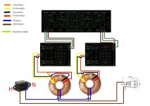
You mean just to twist them together, otherwise connections are correct?Regarding your wiring plan I would rather exchange red with black secondary wires in the diagram.
Thank you for your patience, to be honest I am not too keen on asking basic questions, I could figure it out myself but when it comes to mains I am getting a bit worried things might go not the way I wanted Imagine what would happen if I had connected secondary wires in the wrong order....
When Tiger sent me transformers note stated:
"colour code as below
prim 0 - 240v
blue brown
sec 0 - 15v
black red
orange yellow"
So I assumed blue and black 0, red yellow 15V. I admit I don't know how centre tap works.
PSU board are connected, and wired (temporarily) as in the scheme v2. Pre board is not connected yet.
Imagine what would happen if I had connected secondary wires in the wrong order....When Tiger sent me transformers note stated:
"colour code as below
prim 0 - 240v
blue brown
sec 0 - 15v
black red
orange yellow"
So I assumed blue and black 0, red yellow 15V. I admit I don't know how centre tap works.
PSU board are connected, and wired (temporarily) as in the scheme v2. Pre board is not connected yet.
Attachments
- Home
- Source & Line
- Analog Line Level
- Salas DCG3 preamp (line & headphone)