Be sure to have a fully vented top cover. Depending on your CSS setting you gonna have quite a lot of heat in the area where the two UBIBs heatsinks are facing each other, best is to have the bottom drilled there at least.
Yes, the baseplate and top cover are vented below and above these heatsinks. You can see the slots in the baseplate sticking out past the edge of the heatsinks in the photo.
The heatsinks have pretty decent the thermal capacity, so with the venting I've got, I think I should be ok. The front set of ubibs are set for pretty low current (100ma, of which about 50ma is used), so they will generate very little heat.
Last edited:
Yes 0.8mm
R15 is setting lab standard interconnection ~50Ω Ζο. Doesn't have to be precise, especially in audio. Can be 47Ω or 51Ω when the BOM's 49.9Ω isn't available in a stockist you buy from.
Power dissipation on R10 is 7.5Ω*(0.15Α*0.15Α)=0.169W. Because it brings about 150mA bias. X3 nominal is safe so 0.5W is on the nose. Prefer 1W if available for super cool resistor operation.
Thank you!
I have some Shinkoh TAF 0.5W resistors and their leads are mostly 0.8mm width.
They was a pain to fit..

Salas - I am planning to use your name "SALAS" on the front panel and top cover to "brand" the preamp. I wanted to make sure you were ok with that before I had these panels fabricated.
Thanks,
Jay
I am cool. You explain on the back panel anyway.
I am cool. You explain on the back panel anyway.
Thanks.
When exact diam rub them off with grit paper a little. For the oxides to come off especially in NOS parts, plus losing tiny bit of diameter.
I am afraid to expose copper on tin copper leads.
I guess it must be of high grit number and only a few careful moves.
Will experiment on the end of the leads later.
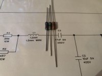
And they won't fit again because leads is 0.8 mm width and width of the hole on PCB is also 0.8 mm.
P.S.: Photo of a few 0.5W resistors with various lead width:
Dale RN60 - 0.64mm
Takman REY 0.5W - 0.7mm
Shinkoh TAF 0.5W - 0.8mm
Yep Shinkoh have strong shelf oxide, Dale RN60 a bit less and Takman looks fresh.
Will try to clean them with chemicals.
P.S.: Photo of a few 0.5W resistors with various lead width:
Dale RN60 - 0.64mm
Takman REY 0.5W - 0.7mm
Shinkoh TAF 0.5W - 0.8mm
Yep Shinkoh have strong shelf oxide, Dale RN60 a bit less and Takman looks fresh.
Will try to clean them with chemicals.
Attachments
Last edited:
I am afraid to expose copper on tin copper leads.
I guess it must be of high grit number and only a few careful moves.
Will experiment on the end of the leads later.
High grit yes, to polish the tin
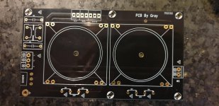
Still enjoying my DCG3 , naturally. It is an amazing preamp. I was going to re house my build and I came upon this neat little pcb on AliExpress. It will save me some space. And best of all it is in Salas/Tea bag black!
Double E cow non the less!?!
£4.82 8%OFF | Double E Cow Power Supply Board Gold Board Suitable For 15-25W Talema Transformer Or Bingzi Green Transformer
Double E Cow Power Supply Board Gold Board Suitable For 15 25W Talema Transformer Or Bingzi Green Transformer|Amplifier| - AliExpress
Double E cow non the less!?!
£4.82 8%OFF | Double E Cow Power Supply Board Gold Board Suitable For 15-25W Talema Transformer Or Bingzi Green Transformer
Double E Cow Power Supply Board Gold Board Suitable For 15 25W Talema Transformer Or Bingzi Green Transformer|Amplifier| - AliExpress
Attachments
In post #1 there are detailed THD plots across frequency on different loads that show 150mA bias is somewhat useful in 32Ω headphones but not in line level situations. It also raises power limit in such a load. Subjectively I didn't find any plausible benefits between 100 & 150mA bias in line level use.
25VA spec is theoretically sufficient although if they have more than average thermal losses they may get warm due to the significant bias constant draw. I have seen that happening with plastic encapsulated 30VA split bobbin frame on DCG3 going about 45C but toroidal usually runs cooler.
- Home
- Source & Line
- Analog Line Level
- Salas DCG3 preamp (line & headphone)