Salas do you have a simple raw DC supply PCB that we could use, for example one with rectifiers and some filtering which we could then connect to a regulator.
I'm planning to build a two-chassis preamp with the transformer, rectifiers and pre-filtering in one chassis, with the DCG3, UBibs, attenuator, etc. in a second chassis.
I've used these boards on a few projects and plan to use again for the DCG3.
Bridge rectification PSU PCB using 4 ultrafast diodes ! - JIMS Audio
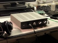
It ended up quite pleasing to the ear but fairly pleasing to the eye also I would think. BTW are you running the MAC OS on a Virtual Machine?Ok, two last photos and then I'll get out of your hair. Excepting eight screws and washers, I think I'm done! That was... quite a project!
-Henry
Salas - I am planning a fully balanced preamp (two DCG3 boards) in a two chassis configuration. The first chassis will house the transformer (custom 400VA Toroidy Audio Supreme with separate secondaries for the two channels, as well as other secondaries for input buffers and selector/attenuator power) and rectifier/capacitor boards. I will use a DC connection to the second chassis, with separate +/- for each channel.
I had planned to use a UBib pair for each phase of the DCG3 (i.e. two UBib pairs for each DCG-3 board), but you mentioned in post 4852 and 4810 that using a single pair for each DCG3 in a balanced config might offer better PS common mode noise rejection. Do you recommend one UBib pair instead of two (per DCG3) for this application?
The DCG3 will always be operating in balanced mode. I will have an input buffer to convert single ended inputs (if I ever use them) to balanced before the attenuator.
Thanks.
Thanks. I remember seeing a post a while back on your recommendation for UBIB setup, but I can't seem to find it.
Assuming ~120ma bias on the DCG3, what should the UBib current limit be set to?
What kind of heatsinks do you think would be necessary for the UltraBibs? Do you think a heatsink with ~5degC/W would be adequate (for each UBib polarity), or should I be looking for something bigger?
Thanks very much for your assistance.
If you will not be using low impedance headphones, set +/- 350mA CCS in the Ubibs. In case you will, +550mA/-350mA. That's typical to cover all it can pull on max out 32Ω bench testing. Balanced drive is like bridging a stereo amp so its headphones output power goes 4X. I don't think you can stand listening to that. No less than 60 Ohm headphones can be still addressed with +/- 350mA even when playing splitting loud.
Can't answer the sinks question from the top of my head, especially when not knowing the final +mA CCS setting choice. There are many thermal exchange guides and calculators online you may look up though.
Your power bases are that M1 in Ubib dissipates Watt=(Vin-Vout)*CCS mA while M2 dissipates Watt=Vout*(CCS-Load) mA. Vin is the Raw DC after rectification. Load is roughly 2X bias since the preamp is Class A and doubled up balanced.
With 120ma DCG3 bias, 350ma UBIB CCS, 17VAC transformer secondary, and 17.3V output from the UBib, I'm estimating approximately 3.8watts between the two mosfets. So using 5degC/W heatsinks should keep temps in the 40-45 degC range which seems OK.
It might be a bit warmer than this in the chassis (even with good vent holes), but I also expect there will be some voltage drop in the DC umbilical cable between the two chassis and in other connections which will cut power a bit.
Thanks again for your help.
It might be a bit warmer than this in the chassis (even with good vent holes), but I also expect there will be some voltage drop in the DC umbilical cable between the two chassis and in other connections which will cut power a bit.
Thanks again for your help.
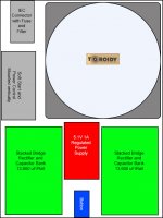
Here is my planned layout of the two chassis. I'm planning to use two Modushop chassis. The power supply will be in 230mm x 280mm Galaxy 2U with aluminum covers. The main preamp chassis will be a Slimline 2U 350mm deep aluminum chassis.
The power supply chassis has a 400VA Toroidy Audio Supreme custom transformer with 4x17V secondaries for the DCG3, 4x12V secondaries for the AMB alpha 24 buffers, and 1x7.5V secondary for the selector/attenuator and OLED display.
I'm planning to use a filtered IEC connector, and a soft-start/power control module. The power supply chassis will also have a regulated 5.2V supply for the Khozmo, and four separate linear power supply boards with bridge rectifiers and 13,600 uF capacitor banks. Two of these will be for the DCG-3s and two for the AMB alpha-24 buffers.
A 14 conductor umbilical cable will connect the power supply chassis to the preamp chassis.
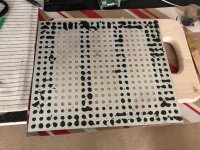
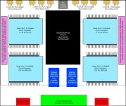
The preamp will use a double Khozmo select/attenuator for fully balanced selection with 3 XLR inputs and 3 RCA inputs. This will feed an AMB alpha24 buffer to provide 1Mohm input impedance (balanced) and 66ohm output impedance to drive the 5K balanced shunt attenuator. It will also do single-ended to balanced conversion for the RCA inputs. The attenuator is built with Takman REY shunt resistors and Vishay Z-foil series resistors.
The output of the attenuator will feed both a pair of DCG3 boards operating balanced, and another set of the AMB alpha 24 buffers. The second set of buffers will be set to the same gain as the DCG-3, and output to RCA and XLR outputs (I expect to use the RCA output to drive my subs).
I'm using four +/- Ultrabib supplies - one for each of the two DCG3 boards, and one each for left and right alpha-24 boards.
I think this should work well for my needs. I've started to collect all the parts, but it will probably take me several months to get this all together (depending on when the UltraBiB GB is ready). Based on everything I've ready about the DCG3 and UltraBiB supplies, I'm really excited about this build.
The power supply chassis has a 400VA Toroidy Audio Supreme custom transformer with 4x17V secondaries for the DCG3, 4x12V secondaries for the AMB alpha 24 buffers, and 1x7.5V secondary for the selector/attenuator and OLED display.
I'm planning to use a filtered IEC connector, and a soft-start/power control module. The power supply chassis will also have a regulated 5.2V supply for the Khozmo, and four separate linear power supply boards with bridge rectifiers and 13,600 uF capacitor banks. Two of these will be for the DCG-3s and two for the AMB alpha-24 buffers.
A 14 conductor umbilical cable will connect the power supply chassis to the preamp chassis.
The preamp will use a double Khozmo select/attenuator for fully balanced selection with 3 XLR inputs and 3 RCA inputs. This will feed an AMB alpha24 buffer to provide 1Mohm input impedance (balanced) and 66ohm output impedance to drive the 5K balanced shunt attenuator. It will also do single-ended to balanced conversion for the RCA inputs. The attenuator is built with Takman REY shunt resistors and Vishay Z-foil series resistors.
The output of the attenuator will feed both a pair of DCG3 boards operating balanced, and another set of the AMB alpha 24 buffers. The second set of buffers will be set to the same gain as the DCG-3, and output to RCA and XLR outputs (I expect to use the RCA output to drive my subs).
I'm using four +/- Ultrabib supplies - one for each of the two DCG3 boards, and one each for left and right alpha-24 boards.
I think this should work well for my needs. I've started to collect all the parts, but it will probably take me several months to get this all together (depending on when the UltraBiB GB is ready). Based on everything I've ready about the DCG3 and UltraBiB supplies, I'm really excited about this build.
Attachments
It ended up quite pleasing to the ear but fairly pleasing to the eye also I would think. BTW are you running the MAC OS on a Virtual Machine?
Thank you. LOL, no. Just playing tricks with photography.
Apropos my comments a while back about the stability of the DCG3, there's a current thread in this sub-forum right now that's relevant:
Phase shift near 180° but still lots of margin?
In particular, the Bode plot in the first post looks just like the one I calculated with SPICE for the DCG3:
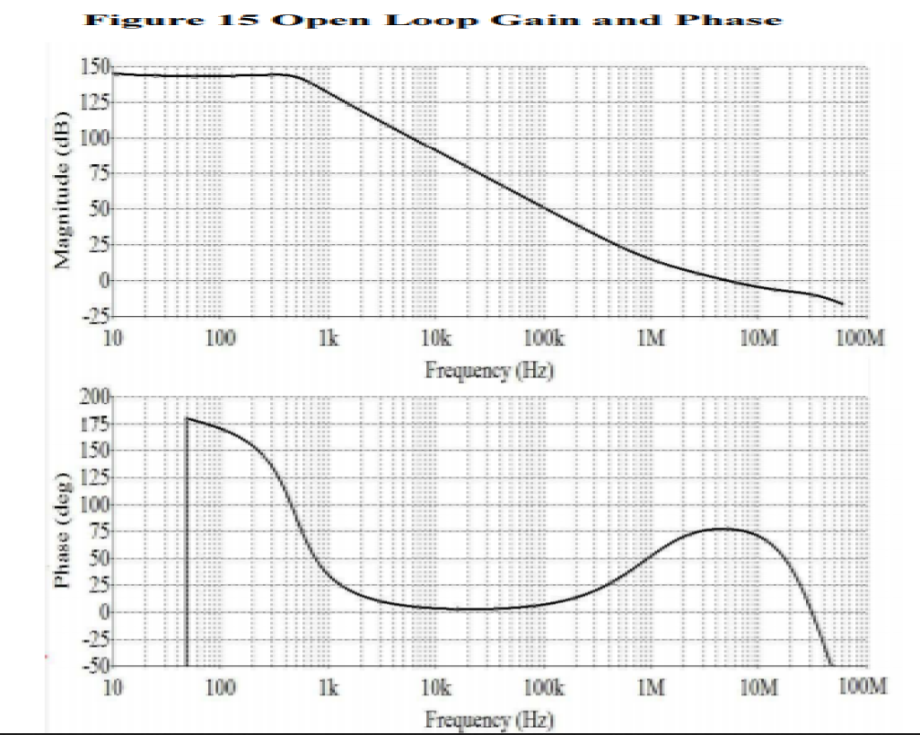
The OP asks how the circuit can be stable when it has close to 180 degrees phase shift at a point where the loop gain is positive. My intuition said it can't, and from what I'm reading this morning, a lot of people think the same. Turns out I'm wrong. The only stability criterion is that the closed-loop transfer function has no poles in the right-half plane. For that to happen, G(s) * H(s) has to be exactly negative one. It's possible for the circuit to hit 180 degrees phase shift at a lower frequency and the feedback will keep the closed-loop response from blowing up.
The bottom line is, at least I understand now why my SPICE analysis doesn't indicate a problem with DCG3. I will try to remove the compensation capacitors I added to my version of the board. I don't expect it will oscillate, but it will be interesting to see if I detect a change in the sound.
-Henry
Phase shift near 180° but still lots of margin?
In particular, the Bode plot in the first post looks just like the one I calculated with SPICE for the DCG3:
The OP asks how the circuit can be stable when it has close to 180 degrees phase shift at a point where the loop gain is positive. My intuition said it can't, and from what I'm reading this morning, a lot of people think the same. Turns out I'm wrong. The only stability criterion is that the closed-loop transfer function has no poles in the right-half plane. For that to happen, G(s) * H(s) has to be exactly negative one. It's possible for the circuit to hit 180 degrees phase shift at a lower frequency and the feedback will keep the closed-loop response from blowing up.
The bottom line is, at least I understand now why my SPICE analysis doesn't indicate a problem with DCG3. I will try to remove the compensation capacitors I added to my version of the board. I don't expect it will oscillate, but it will be interesting to see if I detect a change in the sound.
-Henry
Yep ")
But I did not tweak it on Spice reference since even there it never goes to G=1 with 180 degrees phase shift. That's the instability criterion.
According to SPICE, the caps heavily dominant-pole compensated the circuit, reducing OLG substantially across the entire audible range. I never would have installed them except for the issues I had with the prototype. I'm sure the difference in distortion would be readily measurable and absent a stability problem there's just no reason to leave the caps in, of course.
I want to say it sounds even better now, but frankly my ear isn't that good.
You must forgive me, but for a bunch of reasons this is the first truly high-end sound I've had to listen to in, well, decades. So I'm kind of feeling like a little kid unwrapping gifts on Christmas morning.
-Henry
I want to say it sounds even better now, but frankly my ear isn't that good.
You must forgive me, but for a bunch of reasons this is the first truly high-end sound I've had to listen to in, well, decades. So I'm kind of feeling like a little kid unwrapping gifts on Christmas morning.
-Henry
- Home
- Source & Line
- Analog Line Level
- Salas DCG3 preamp (line & headphone)