Hey Nick,
I’d like to change R1 to 2.2k, and R2 100k. I really believe this would be a better match for my dac which so much better with a 10k pot. What would I want to change C1 to?
Cheers,
Greg
Maybe 15pf. The input filter R1 C1 is a guard for the pre-amp not to oscillate on incoming wires inductance and/or low to zero source impedance. Its at a delicate balance with the rest of the frequency compensation phase margin and a part of it. Do you have an oscilloscope to confirm all is well at the output after changes? If not and when there is a problem maybe audible buzz will appear and/or the sound will go seriously downhill. Be careful.
So, that tells me, and exactly what Tea said: a single mono BiB is simply not enough to power this circuit properly.
In a Greek forum a member moved from single shared UltraBiB to dual mono UltraBiB for his diy headphones preamp (he did not mention which one) and yesterday he reported VERY enthusiastically about some significant subjective upgrade. Maybe that extra PSU addition could also help your DCG3 to the same extent or less (?)
In a Greek forum a member moved from single shared UltraBiB to dual mono UltraBiB for his diy headphones preamp (he did not mention which one) and yesterday he reported VERY enthusiastically about some significant subjective upgrade. Maybe that extra PSU addition could also help your DCG3 to the same extent or less (?)
Hey Salas,
Being the the speaker geek that I realized I was getting some slap reflections with my ML Montis (not enough rake). This has Warmed up my system considerably. The DCG3 will be reintroduced and I think all of the brightness will be gone. Just breaking in some buffer tubes in my dac right now. I don’t want to try the DCG3 until they have cycles and hours.
The DCG3 is a heck of a good design, so I can’t wait to try it again.
As far as psu goes, I may change my mind when I try the new speaker setup. It’s just a lot warmer now, the kind of warm that you listen to all day with no fatigue, and I didn’t lose any detail. So, we are much better prepared for your board.
I will certainly report back. I will probably try it tomorrow.
Cheers,
Greg
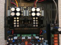
Well, I have finally put my DCG3 together with dual mono DCSTB supplies and got it to the stage of everything looking good on electrical testing. Power supply regulators are running at ~ 45 degrees as are the output MOSFET's - that's after about 2 hours continuous on time. Bias is at 152.8 mA left channel, 153.5 mA right, dc offset trimmed to less than 1mV before fitting the opamp and it's still below 1mV on both sides with the servo working. The 'hot' bias is due to 50 ohm headphones to drive (Senheisser HD598SR's).
I'm also running the In-Select board for input selection with the 20K Alps blue pot - again this all looked fine when powered up from raw AC input (~20V) off one transformer secondary. The LED lit up and I measured 12.2V on the Vreg out, so far so good BUT this is where the problems started. I wired up the selector switch, ran the In-Select ouput to pre inputs and grounded the pot body, powered everything up and got smoke ! Diodes D3 and D4 on the rectifier of the In-Select are fried; I assume that somewhere I had a short and pulled way too much current but I can't see any errors on the board after taking all my wiring off. Both the DCSTB and DCG3 boards seem fine, all running as before so I think the damage is to the In-Select only. Will the 7812 be fried as well? Measuring across the output pads I only have 1.5 to 2 ohms between R or L and the centre ground pad - is that normal or have I killed a relay as well?
In the meantime while I wait for new bits for the selector board, is there any way I can see if the DCG3 plays music? If I use my phone as the input on minumum volume will the output to the headphone socket be too high without the pot in the circuit? I don't want to blow anything else up but I'd love to hear the sound of this amp
I'm also running the In-Select board for input selection with the 20K Alps blue pot - again this all looked fine when powered up from raw AC input (~20V) off one transformer secondary. The LED lit up and I measured 12.2V on the Vreg out, so far so good BUT this is where the problems started. I wired up the selector switch, ran the In-Select ouput to pre inputs and grounded the pot body, powered everything up and got smoke
! Diodes D3 and D4 on the rectifier of the In-Select are fried; I assume that somewhere I had a short and pulled way too much current but I can't see any errors on the board after taking all my wiring off. Both the DCSTB and DCG3 boards seem fine, all running as before so I think the damage is to the In-Select only. Will the 7812 be fried as well? Measuring across the output pads I only have 1.5 to 2 ohms between R or L and the centre ground pad - is that normal or have I killed a relay as well? In the meantime while I wait for new bits for the selector board, is there any way I can see if the DCG3 plays music? If I use my phone as the input on minumum volume will the output to the headphone socket be too high without the pot in the circuit? I don't want to blow anything else up but I'd love to hear the sound of this amp
Something wrong with the AC secondaries interaction probably. Was the selector board fed from an independent secondary? Is there a picture of the whole as wired when failing? Raw DC from a DCSTB's reservoir capacitor can be fed to selector board instead of AC as well. It has DCin also. Presuming that its components are in good condition. What is the exact type of relays you used? You can have low Ohm reading across the output when the pot is fully closed.
You can wire just a pot between a single input and the pre-amp to listen. From a controlled phone output also sans pot but make sure you start at low vol. You can check with the DMM in AC mode before hooking up the cans for no more than 150mV RMS output with a 300Hz sine tone input from some freq generator app. So you make sure it won't be very high and dangerous. Your cans do 94dB SPL with 134mV RMS only.
You can wire just a pot between a single input and the pre-amp to listen. From a controlled phone output also sans pot but make sure you start at low vol. You can check with the DMM in AC mode before hooking up the cans for no more than 150mV RMS output with a 300Hz sine tone input from some freq generator app. So you make sure it won't be very high and dangerous. Your cans do 94dB SPL with 134mV RMS only.
A good practice is to put a resistor, say 5-10 ohm that brings the voltage slightly down 1 or 2 volts, before the PSU, when firing for the first time, as well as testing units independently as much as possible before putting them all together.
works with me anyway
works with me anyway
Last edited:
I used a dim bulb tester when I first powered the boards up and everything was fine - sadly I didn't do this again after I'd added the signal wiring between the selector and amp boards.
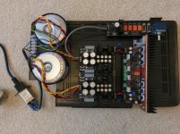
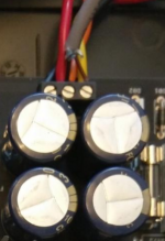
I've attached a few photos - it's breadboarded as you can see and the grey wire supplies roughly 20V ac from a single secondary on that transformer to the selector board. I'd already taken the signal wiring back off so that I could inspect the selector board before I took these pics. I'll try to describe the extra wires I had so you can tell me which was the stupid one! Selector board output had two screened twisted pair cables soldered on, one per channel, ground common between the channels. These ran to the DCG3 input headers and yes I did check that ground went to ground. The pot had a wire looped round the shaft housing held on by the nut and running to the 0V header on the Vreg out pads of the selector board - this is on the same trace as the ground for all of the switch contacts. The selector switch was wired to the board with the appropriate centre contact to ground and inputs 1-4 to switch contacts 1-4 - it's a 2 pole switch and I'll use the other half of it to run source indicator LEDs in the final build. There was also a wire from the common ground trace along the front of the DCG3 to the 0V header on the Vreg out pad of the selector board so that both boards saw the same audio ground. That front ground trace also connects by the power connectors to the transformers centre tap (I think) or in my case the common ends of the dual secondaries. I hope that makes sense of what I did, clearly it didn't make sense to the electrons!
I've attached a few photos - it's breadboarded as you can see and the grey wire supplies roughly 20V ac from a single secondary on that transformer to the selector board. I'd already taken the signal wiring back off so that I could inspect the selector board before I took these pics. I'll try to describe the extra wires I had so you can tell me which was the stupid one! Selector board output had two screened twisted pair cables soldered on, one per channel, ground common between the channels. These ran to the DCG3 input headers and yes I did check that ground went to ground. The pot had a wire looped round the shaft housing held on by the nut and running to the 0V header on the Vreg out pads of the selector board - this is on the same trace as the ground for all of the switch contacts. The selector switch was wired to the board with the appropriate centre contact to ground and inputs 1-4 to switch contacts 1-4 - it's a 2 pole switch and I'll use the other half of it to run source indicator LEDs in the final build. There was also a wire from the common ground trace along the front of the DCG3 to the 0V header on the Vreg out pad of the selector board so that both boards saw the same audio ground. That front ground trace also connects by the power connectors to the transformers centre tap (I think) or in my case the common ends of the dual secondaries. I hope that makes sense of what I did, clearly it didn't make sense to the electrons!
Attachments
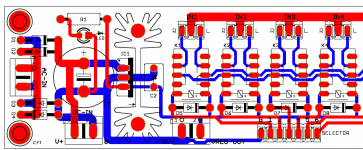
Diodes D3 and D4 on the rectifier of the In-Select are fried; I assume that somewhere I had a short and pulled way too much current but I can't see any errors on the board after taking all my wiring off.
D3 & D4 on the selector board are to its ground. They made passage for the floating AC to its own CT as soon as that board's ground came in contact with the system's common ground. Use one AC leg and CT. Replace those diodes also of course. Check that the zero blue trace did not burn off. Visually and with the DMM's continuity buzzer.
Attachments
Hi Salas, thanks for the speedy help.
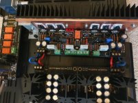
The grey wire is across one ac to ct only - clearer photo attached. Voltage across both ac is just over 40V - the 7812 would definitely have gone up in smoke if I'd done that. Does the black ct wire need to go to the ac in terminal next to D3/D4? Just noticed that at the moment it's the brown wire from the other end of the secondary that is closest to D3/D4 - as these run to ground perhaps this is the cause of the short?

The grey wire is across one ac to ct only - clearer photo attached. Voltage across both ac is just over 40V - the 7812 would definitely have gone up in smoke if I'd done that. Does the black ct wire need to go to the ac in terminal next to D3/D4? Just noticed that at the moment it's the brown wire from the other end of the secondary that is closest to D3/D4 - as these run to ground perhaps this is the cause of the short?
Hi Salas, thanks for the speedy help.
The grey wire is across one ac to ct only - clearer photo attached. Voltage across both ac is just over 40V - the 7812 would definitely have gone up in smoke if I'd done that. Does the black ct wire need to go to the ac in terminal next to D3/D4? Just noticed that at the moment it's the brown wire from the other end of the secondary that is closest to D3/D4 - as these run to ground perhaps this is the cause of the short?
There was also a wire from the common ground trace along the front of the DCG3 to the 0V header on the Vreg out pad of the selector board
It does look like across the AC connector in the previous pictures. Tricky pics. Make sure of your transformers secondary wires colors and rearrange as you wrote. But I don't think that's the key. Still don't use that DCG3 0 to DCout 0 selector board wire again. That's my suspicion now that you cleared its not about feeding across AC AC.
Attachments
I agree that the photo looks a bit misleading (pun intended ) - sorry for the confusion. I will replace D3/D4, check track continuity as suggested and re-wire the signal inputs without the connection from amp common ground to selector 0V point. I'll also make sure I've got the dim bulb tester in circuit when I power up again.
Thanks again for your help; I'm fairly sure I have some suitably rated diodes in my bits pot but will double check the data sheets and order new ones if needed. Once I've got it up and running I'll post an update and buy a proper chassis. I'm intending to take a wire from the amp common ground via an earth loop breaker to the protective earth bolt - is this a good idea or would it be better to use the selector 0V point for the earth attachment?
) - sorry for the confusion. I will replace D3/D4, check track continuity as suggested and re-wire the signal inputs without the connection from amp common ground to selector 0V point. I'll also make sure I've got the dim bulb tester in circuit when I power up again.Thanks again for your help; I'm fairly sure I have some suitably rated diodes in my bits pot but will double check the data sheets and order new ones if needed. Once I've got it up and running I'll post an update and buy a proper chassis. I'm intending to take a wire from the amp common ground via an earth loop breaker to the protective earth bolt - is this a good idea or would it be better to use the selector 0V point for the earth attachment?
You may use any 1N4xxx diodes to replace those. The DC in/out 0V on the selector board is the relays PSU ground, not a signal ground. Signal ground is the middle points common line along its inputs and output connectors. The dim bulb tester is going to help save the day in most cases. A loop breaker is not a bad idea either. Good luck and let us know.
Salas,
Reintroduced the DCG3 after a very minor speaker adjustment. Got rid of the slap reflections.
Take a deep breath, calm down....its awesome. Amazing dynamics, liquid smooth. No harshness, just a lot of micro detail and balanced from top to bottom. I thunkbthe 327 mod is essential. Running the AD823. Will do a proper review when broken in.
Good lord, though, easily one of the best I have ever heard. Very forward, huge space between recording elements. Its passing all of my harshness tests. Its just good, enjoyable, dynamic, listening.
Tea/Salas, thanks for all you do.
Very nice subjective feedback from a seasoned system with big electrostatic speakers. Thanks for letting us know. Waiting for your full review. Maybe there's even more performance hidden there to be revealed when you will move from single shared to dual mono UltraBiBs.
Nick,
I'm going to stick with the mono BiB setup for the time being. The depth, clarity, and non-congested sound field I'm getting is very similar to my hotrod DCB1, just with warmth and an even presentation. With the DCB1, its super resolving, but the presentation is all over the place because of recording difference. The DCG3 is about as resolving, with proper smoothness, dynamics and control. The DCG3 gives about theoretical maximums in all categories.
Plus, I'm just not excited about shoe-horning another BiB set into the chassis. I've got great power and low temps with my single mono setup.
Cheers,
Greg
Very nice subjective feedback from a seasoned system with big electrostatic speakers. Thanks for letting us know. Waiting for your full review. Maybe there's even more performance hidden there to be revealed when you will move from single shared to dual mono UltraBiBs.
Dual mono here I come! With your support, who can ever say no. ;-)
Humble plug & play DCSTB is already dual mono nonetheless. Alright, its not a fire breathing CCS biased shunt reg but a very decent low noise discrete series thing complete with onboard sinks that nails the tonality. Non reactive and cute, it also has the best lights
But not as cool!!!!
Just pm'd Tea for the DCSTB. Hopefully he has a kit left....
- Home
- Source & Line
- Analog Line Level
- Salas DCG3 preamp (line & headphone)