Thank you Salas and Bambadoo! I fixed the PS with a BC546 I had in a bin. So running well now. I have a slight missed level when selecting an open input.
I'll try to isolate the audio ground from chassis and/or connect the audio ground on the in-select board to the chassis.
I'll try to isolate the audio ground from chassis and/or connect the audio ground on the in-select board to the chassis.
Attachments
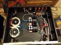
Looks like a sturdy build. Good fix with the BC546. The Fostex TH900 very nice. What do you mean by "a slight missed level when selecting an open input"? How you know there is slightly lower level when selecting, thus playing, nothing? Do you mean selecting a non source connected input or one of those two completely empty relay positions? I connect PCBs zero to chassis (if its better) at the input side usually, selector/pot, not at the PSU's zero.
I meant: if an open input is is selected there is a low level of noise present at the outputs, this is nothing connected to the input.
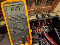
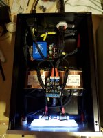
I measured 8.35 volts DC between the "0" volt terminals in the power supply of the selector board to ground, that is what caused the overload of the DCSTB previously. I'm leaving that floating since it only powers the relays.
Thanks again!
I measured 8.35 volts DC between the "0" volt terminals in the power supply of the selector board to ground, that is what caused the overload of the DCSTB previously. I'm leaving that floating since it only powers the relays.
Thanks again!
Now its an independent supply for the relay coils. Fed from AC with its own rectification, storage, and chip reg, but if its "zero" isn't referenced to the chassis it can gather some interference that will eventually radiate from the coils to the relay signal contacts and to the PCB signal tracks which pass in very close proximity and can become audible. See with a crock lead if such a reference can eliminate the slight noise you detect with no source input selected. In other words when the impedance is high and interference has it easier to couple.
Now its an independent supply for the relay coils. Fed from AC with its own rectification, storage, and chip reg, but if its "zero" isn't referenced to the chassis it can gather some interference that will eventually radiate from the coils to the relay signal contacts and to the PCB signal tracks which pass in very close proximity and can become audible. See with a crock lead if such a reference can eliminate the slight noise you detect with no source input selected. In other words when the impedance is high and interference has it easier to couple.
Thanks Salas. Pardon my ignorance, what is a "crock" lead?

I tried to connect the "0" volts for the input board to ground, it sparks and overloads the transformer secondary where it is getting its power from.
This means there is something amiss in the input board. I am going to take a closer look to see what is causing this problem.
Crocodile ends lead I wanted to say. But added a k typo. But you did try with a wire already as you say.
duh!
 .
.
I believe is correct.
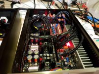
See about chasing that when no source selected slight noise. By signal's zero reference to chassis at the pot's 0 pin than at the 0 of left rails that now is or through a 10 Ohm resistor where it is now or to float.
Hi Salas
I want to repair an old Yamaha integrated that has a fault in the preamp section so only the power amp is usable.
I still have one board to build a DCG3 and have no upa68 left.
I have some K117 that I can match but I also have a couple of LSK 489... would the LSK be suitable for this build ?
What is the difference between the LSK 389 and LSK489 ?
Use 2SK117s that have the right Gfs etc. The THD trends are very close to the μPA result.
LSK489 withstands 60V across and has much lower transconductance, but much less capacitance, and moderately more noise than the LSK389. Thus the LSK489 is more suitable for power amplifiers input stages and for whatever is driven from a high source impedance.
LSK489 withstands 60V across and has much lower transconductance, but much less capacitance, and moderately more noise than the LSK389. Thus the LSK489 is more suitable for power amplifiers input stages and for whatever is driven from a high source impedance.
Bargraph Leds. No need to match Vref Leds for DCG3 because it does not care about exact same +/- rails. Bar Led packs are compact, straightforward to solder, looking great.
Salas,
for PSU regulator, why you didn't use one led of 2 V, but Instead you choose bar graph leds that take space
Is It Important noise level of reference element at that location
Because this is a unity gain Vref, nothing active is there for amplifying one LED to higher voltage. Several are required to reach the output goal (-Vbe). Yes, their self noise level is important that is why the bar is filtered by capacitors. LEDs are considered low noise voltage sources in general. Noise sources in series sum in RMS format. Ten LEDS isn't ten times the noise of one but square root that product. With the BOM's filter capacitors this PSU circuit simulates for 6.5nVrtHz at 20Hz, 1nVrtHz at 70Hz, 0.21nVrtHz at 1kHz, 0.18nVrtHz at 20kHz spot noise on output.
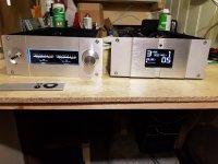
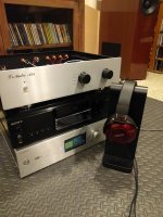
Hey TWST great work, especially nice the digital display OLED screen. Congratulations! What the Vu meters in the PSU box read for? Looks like it doubles as a control box. For what rest of system is to be blended in and did you have the chance for a listen yet?
Thanks!
I am pleased with the screen myself, it really completes this preamp. Took a lot of drilling and filing by hand making that hole
The VU meters just reads a non calibrated peak power output from both channels. Hooked up to the HP output. I just thought it would be nice having something moving and analog while music plays. Just for the looks and not really useful.
You are correct, PSU box faceplate doubles as a control box and interacts with the display for volume and inputs.
I had a brief listen yesterday in my basement system. Hooked up to Klipsch RF62II through Aleph 30 monoblocks. First reaction is amazing clarity and 3D image! Bass is deep and tight with all the black background I will ever need! Will need more time with it for further sonic comments, and I guess the circuit need some burn in. But all very promising
Today I will hook it up into my main system. Klipsch Heresy III fed by a newly built dual mono Aleph J. Replacing a Cary clone 6SN7 preamp. Coming from tubes, I hope the clarity does not make it too forward sounding - but I guess my ears adjust either way while it's burning in
- Home
- Source & Line
- Analog Line Level
- Salas DCG3 preamp (line & headphone)