I logged-in, wrote a reply for 6A3 Summer (et al) on high voltage deaths including TV EHT as well as 'microwaves' and when submitting was advised 'you have not logged in". WHAT!!,,,I could not recover my work. Grrrrrrr!!...I'm not going to rewrite now...is there some limitation of writing time once logged-in?
Please advise.
Please advise.
We need an automatic login, like Antique Radio Forum has.I logged-in, wrote a reply for 6A3 Summer (et al) on high voltage deaths including TV EHT as well as 'microwaves' and when submitting was advised 'you have not logged in". WHAT!!,,,I could not recover my work. Grrrrrrr!!...I'm not going to rewrite now...is there some limitation of writing time once logged-in?
Please advise.
Cheers,
Roger
kirwanrebel,
I am sorry for your trouble.
In the old US Navy, there were more shipboard deaths from 110-120VAC than from all the other electronic equipment.
Shipboard has all kinds of very excellent "Ground" metal return points in/on the ship.
There was more access to 110-120VAC equipment.
There was less respect for that equipment and voltage.
The Radars, High Power Sonars, High Power Transmitters, etc. were maintained by persons that were carefully taught safety rules.
And there were devices, including insulated handle grounded shorting bars, etc.
When I was in a support group, we got all kinds of calls from customers who wanted to float their scopes and other test equipment.
I always advised against that (not just safety, but measurement results could be way off because of the parameters involved).
They would say what could happen.
I would quote the surviving spouse syndrome:
The surviving spouse now owns your company.
I even got calls from new employees of a safety company that wanted to violate their own safety rules in order to make a measurement.
And, if you made a measurement that gave the wrong results, the airplane may crash.
Lawsuit anybody?
Last edited:
Hello,
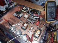
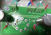
I am building a little tube amplifier that work with 670 volts dc . Some cables have to pass through a red copper piece of metal ( there are two copper chassis bolted to each other. One is signal and one is power supply. I can isolate the cables in the two chassis with adding an extra teflon tube around the already teflon covered cable and by using some physical distance between two cables that would create a short circuit while touching.
I wonder how to improve isolation in the area where the cables are passing through the copper without making to big holes. Probably needs to be something like teflon, ceramic, glass. Could be something that is used for something completely different outside audio life.
Greetings, eduard
Attachments
I'd use HV wire and a small rubber grommet and call it a day.
Something like this: 10m High Voltage Wire 6KV 6KVDC VW-1 TV-6 3472 AWG22 105℃ UL CSA Sumitomo Japan | eBay
Something like this: 10m High Voltage Wire 6KV 6KVDC VW-1 TV-6 3472 AWG22 105℃ UL CSA Sumitomo Japan | eBay
Hello,
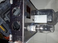
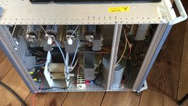
I decided to get some PTFE round massive tubes which i can mill ( if needed) to the same diameter as the drilled holes in the wood panel that is between the two copper chassis. After drilling a hole in the center of the PTFE i just gentle push it into the wood. This way the isolation of the cable itself can never get damaged if the holes in the copper might have sharp edges.
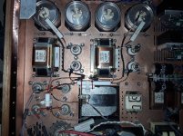
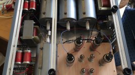
I found the way how to wire the heater supply and how to let them run through the chassis. The heater wires are running between the anode choke and the output transformer close to the chassis ( top plate)What about the rest of the cables. The loudspeakers terminals are on the right side ( 2 times 3 holes in a row) What i could do is make the cable go up from the output transformer secundairy solder tags and when they arrive at the bottom plate let them make a 90 degrees turn towards the side of the chassis.
There is just one input tube ( e80cc/6085). Each half connected to the Vt25A tube. The xlr input terminal will be mounted on the location where there is the small rectangular hole ( At the right corner )
Thanksalot. Greetings, Eduard
I decided to get some PTFE round massive tubes which i can mill ( if needed) to the same diameter as the drilled holes in the wood panel that is between the two copper chassis. After drilling a hole in the center of the PTFE i just gentle push it into the wood. This way the isolation of the cable itself can never get damaged if the holes in the copper might have sharp edges.
I found the way how to wire the heater supply and how to let them run through the chassis. The heater wires are running between the anode choke and the output transformer close to the chassis ( top plate)What about the rest of the cables. The loudspeakers terminals are on the right side ( 2 times 3 holes in a row) What i could do is make the cable go up from the output transformer secundairy solder tags and when they arrive at the bottom plate let them make a 90 degrees turn towards the side of the chassis.
There is just one input tube ( e80cc/6085). Each half connected to the Vt25A tube. The xlr input terminal will be mounted on the location where there is the small rectangular hole ( At the right corner )
Thanksalot. Greetings, Eduard
Attachments
As always, bleeder resistors are needed.
You need to calculate the time constant of the capacitance and bleeder resistance, and determine how long the discharge time is reduced to 42V or less. Even at 42V, it still can be dangerous, but that is one safety standard's recommendation.
R X C = one time constant.
In one R X C time constant, the voltage collapses to 36.3 percent of the original B+ voltage.
In two time constants, the voltage collapses to 13.2 percent of the original B+ voltage,
and in 3 time constants, the voltage collapses to 4.8 percent of the original B+ voltage.
Take a total capacitance, C, of 100uF, and a bleeder resistance, R, of 50k Ohms.
One time constant is 5 seconds; 3 time constants is 15 seconds.
A 600V supply with 100uF and 50k Ohms, R X C, will collapse to 4.8 percent of 600V = 28.8V after 15 seconds.
That is just about the time from turning the amp off, and then removing 6 screws off of the bottom plate of the amp.
Do not forget to add All the capacitances in the CLCRCRC filter, etc.
You have to discharge all the capacitors.
That may be lots more than 100uF.
At 600V and 50k Ohms, we have (600V) squared / 50k Ohms = 7.2 Watts.
Use at least a 25 Watt resistor.
As always . . . Safety First!
Last edited:
Hello,
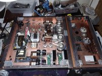
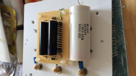
Because i am using a choke input power supply most of the time i am used to use a bleeder resistor to assure that there is always a minimum current running whenever it is switched on. There isnt much capacity used ( total for the stero amp 20 microfarad for the first cap after the infut choke than for left and right each their own LCRC with 50 and 22 microfarad on each side) So total amp 164 microfarad with lowest voltage at the 22 cap is around 620 volts. The 50 microfarad 1000 volt cap has a maximum pulse current 1200 A . Of course with 660 volt on that capacitor the current will be lower but still lethal.
The caps are at 0 volt in a few seconds could even be one or two seconds.
Greetings, Eduard
P.s as you can use i used some teflon/ptfe to create extra safety for keeping high voltage wires in the same place
Attachments
Request for guidance, and a comment.
I am preparing to solder components for my first tube amplifier.
Question: is this irresponsibly risky, and if so, what can I do to reduce risk to a responsible level? Is it even possible? This is probably one of those "if you have to ask, don't do it" questions.
I am 68 years old, and this is my fourth tube-type circuit build. The first was a Heathkit radio, in the early 1960's, and I still have it. The other two were in the 1970's, and I barely remember them. I built them with a friend who was an electrical engineer. He maintained our local NPR transmitter in a college town.
I have re-started an ancient project to build a tube audio amplifier. The pile of parts looks near to enough that I can assemble a working unit, including a pair of Universal Driver boards from Tubelab_com. Maximum voltages will be in the 350 V range. I will start around 280-300 V and go up only if necessary, and then only to 350 V
I recently bought two of Morgan Jones' excellent books - Valve Amplifiers, 3d ed., and Building Valve Amplifiers. I just finished reading them cover-to-cover, and scared myself silly.
I do not have an experienced electronics tech or engineer to sit with me while I tinker. My workshop is in my basement. The only person that would be around if something goes wrong is my wife. She is disabled. She gets around well enough, but cannot come down the stairs into the basement.
What options do I have?
Less important question - I have seen breadboarded amps in the Photo Gallery that used relay bases for octal tube sockets(25th December, 2019). I have several relay bases. For B+ voltages in the 300-350 Volt range, are these things safe as tube bases, solely as short-term prototyping equipment, never to be left unattended?
Second question: I have an industrial control transformer that I want to use as an isolation transformer. [Input: 110, 220/ Output 110, 220, 440] I don’t want a guarantee – nobody on this board makes guarantees, but is this unreasonably unsafe, or should I find something that has “isolation transformer” printed on the outside of it?
Also: the technique of putting a 40 or 60 Watt lamp bulb in series with the mains transformer works a treat. I highly recommend it.
I was testing unmarked transformers to see what I had. I was using probes because I couldn’t find my clip-on test leads. I had one hand in my pocket. I used an alligator clip to clamp down one probe, and I held the other. The VOM probe slipped and I shorted the transformer outputs together.
There was only a small flash. The 40 W bulb went to full brightness, and the lamp extinguished the arc before metal transferred. Not perfect, but very reassuring. It won’t keep you from getting a possibly fatal shock, but it handily protected all the components I was using.
p { margin-bottom: 0.1in; line-height: 120% }
I remember my first valve pre amp when I was learning electronics.
I built it up then turned it on.
It didnt work so I turned it off and touched the circuit getting a nasty shock.
My tutor informed me that the capacitors on valve amps can stay charged up for a good time after power down. He recommended discharging cap through a resistor.
So next I discharged the cap through a resistor.
Got another shock, forgot to turn it off.
Remarkably that was 40 years ago and I am still alive.
I learned quickly to add a resistor and LED across the cap to show when it is live.
And basically just take extra care before touching.
Request for guidance, and a comment.
I am preparing to solder components for my first tube amplifier.
Question: is this irresponsibly risky, and if so, what can I do to reduce risk to a responsible level? Is it even possible? This is probably one of those "if you have to ask, don't do it" questions.
-There's always some risk associated with electricity but you can mitigate it by safe practices. First, use a 200 watts lamps in series with your amp. 40 watts tend to be a little low.
Second, never touch anything with you left hand ONLY right. Keep your left in your pocket.
Third if you're alone, keep a phone nearby or some sort of alarm to call for help if required.
Forth check your industrial control transformer that you want to use as an isolation transformer to make sure the output amperage is sufficient for your amp. If it's only one or two, obviously, not enough. If you don't know, try the 200 watts bulb on it. If it glows shiny, without heating the transformer, it's probably ok.
Fifth I saw those socket. I think they had the orientation pin in it. Probably ok for testing but for the final built, I would order proper socket.
Sixth BEWARE of charged caps. Always wait a proper time and make sure you discharge the large caps. They have a tendency to rebuild the charge once left sitting (mirror charge). Use a 5 watts, 100 ohms resistor for that.
Are you making a single end or a push pull amp ? Stereo or mono ?
Make sure you read a lot on BIASING the output tube. It's very important you set it properly so you wont redburn the tube.
Take car, have fun.
I am 68 years old, and this is my fourth tube-type circuit build. The first was a Heathkit radio, in the early 1960's, and I still have it. The other two were in the 1970's, and I barely remember them. I built them with a friend who was an electrical engineer. He maintained our local NPR transmitter in a college town.
I have re-started an ancient project to build a tube audio amplifier. The pile of parts looks near to enough that I can assemble a working unit, including a pair of Universal Driver boards from Tubelab_com. Maximum voltages will be in the 350 V range. I will start around 280-300 V and go up only if necessary, and then only to 350 V
I recently bought two of Morgan Jones' excellent books - Valve Amplifiers, 3d ed., and Building Valve Amplifiers. I just finished reading them cover-to-cover, and scared myself silly.
I do not have an experienced electronics tech or engineer to sit with me while I tinker. My workshop is in my basement. The only person that would be around if something goes wrong is my wife. She is disabled. She gets around well enough, but cannot come down the stairs into the basement.
What options do I have?
Less important question - I have seen breadboarded amps in the Photo Gallery that used relay bases for octal tube sockets(25th December, 2019). I have several relay bases. For B+ voltages in the 300-350 Volt range, are these things safe as tube bases, solely as short-term prototyping equipment, never to be left unattended?
Second question: I have an industrial control transformer that I want to use as an isolation transformer. [Input: 110, 220/ Output 110, 220, 440] I don’t want a guarantee – nobody on this board makes guarantees, but is this unreasonably unsafe, or should I find something that has “isolation transformer” printed on the outside of it?
Also: the technique of putting a 40 or 60 Watt lamp bulb in series with the mains transformer works a treat. I highly recommend it.
I was testing unmarked transformers to see what I had. I was using probes because I couldn’t find my clip-on test leads. I had one hand in my pocket. I used an alligator clip to clamp down one probe, and I held the other. The VOM probe slipped and I shorted the transformer outputs together.
There was only a small flash. The 40 W bulb went to full brightness, and the lamp extinguished the arc before metal transferred. Not perfect, but very reassuring. It won’t keep you from getting a possibly fatal shock, but it handily protected all the components I was using.
p { margin-bottom: 0.1in; line-height: 120% }
Last edited:
This might be frowned upon by those with genuine knowledge of electronics...
I recently finished building my first tube amp. The way I populated the PCB, my resistors are on top, and the board itself is beneath the chassis top. I needed to measure some voltages to be sure that my power tubes were operating below max dissipation, etc.
I was really nervous about probing in a live amp, so I temporarily soldered on some test leads to the underside of the board. This allowed me to attach my alligator clips while the amp was off. I was able to take the necessary measurements without ever having to be near the live amp. Plus, if anything was to blow up, or catch fire, I was some distance away, and could kill the power from a remote power strip switch. It really eased my anxiety, as this was the first time I had ever worked on a tube amp.
Of course, if you have access to the component leads, this is all unnecessary!
At any rate, I wanted to share this since there may be others who are apprehensive about that first encounter with lethal voltages.
David
Attachments
I am scared too when powering up a finished amp for the first time, therefore i do this in steps. First all the low voltages and if these are all ok then the high voltage. In some cases i use voltage dividers if i expect very high voltages.last week i finished my direct drive amps for my esl’s. 3kv on the anodes.
Attachments
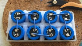
I am scared too when powering up a finished amp for the first time, therefore i do this in steps. First all the low voltages and if these are all ok then the high voltage. In some cases i use voltage dividers if i expect very high voltages.last week i finished my direct drive amps for my esl’s. 3kv on the anodes.
On my first adventures into SMPS I quickly learned to hide behind a chair and switch it on remotely. Mosfets/capacitors flying over your head is no fun.
Nigelwright7557, dwinstonwood, Lampie519, Serge Dufour
Thank you all for your replies. I am carefully considering all of your comments.
After thinking about it, I believe I have a solution to my concerns about having a responsible person available while working on my amp.
I can lug all the currently necessary equipment up to the kitchen when I am working on it. It will be inconvenient. If I don’t have time to do that, then I don’t have time to be working on this at all.
There will be a “kill” switch on the mains cord. I will show my wife the indicator lights and what they mean. She cannot do wind sprints up the stairs, but then again, neither can I. She can get around quite well, as long as there are no steps, and she has quick and easy access to the telephones.
Wife Acceptance Factor is not a problem. Provided I put it all away when I am done, my wife will briefly tolerate chaos in the kitchen in return for knowing she can hear me and get help if something goes wrong.
Nigelwright7557, I will use your resistor and LED trick on the power capacitors, in addition to the bleeder resistors.
There will also be a DPDT switch-box with LED indicator lights showing when there is power on the line, on either leg (i.e. plugged in). There are more lights showing when the switch is “On”. As long as I am installing one anyway, the cost of an additional LED or two is negligible. The chances of two failing simultaneously, is vanishingly small.
Touching the amp; touch controls or instruments only, right hand only, when it is on. “Off” and unplugged, right hand only, when touching anything else inside the housing. While bread-boarding, there will be no housing, so everything connected to the amp will be “outside”.
When testing, attach instrument lead wires, plug in the mains cord, then switch on mains power. When test is complete, switch off power, then unplug. Quick visual check of capacitor LEDs before touching anything.
I have proper sockets for the final build.
Test leads on the circuit board sound like a good idea. I will have to think about which points are necessary.
Basic design is fairly simple. Stereo with push-pull monoblocks and remote power supplies. Two umbilicals for power supplies – one for heaters, the other for driver-tube/MOSFET/power-tube HV.
I bought a couple of Universal Driver Boards from George at Tubelab_com, and will be using those. I am going to try crazy/dual drive, but it is more important to me to use 6CD6’s than to get crazy/dual drive to work. Plain old grid 1 power tube drive is the obvious alternative, and will probably be the final result.
Rough plan of assembly – source and assemble amp circuits, source and assemble power supplies, test and verify power supply voltages with Variac. Power up driver circuits w/o tubes and verify voltages. Add driver tubes and verify voltages. Verify power tube inputs have signal and proper voltage. Add power tubes, and pray for no smoke.
p { margin-bottom: 0.1in; line-height: 120% }
... A year or so later working in an industrial concern I worked on a sub-board whilst jammed in between metal lockers and a switchboard. I'd turned off the main switch and fitted a warning tag which should not be removed without my signature. I worked as always on a dead board as though live, at which I'd become pretty skilled. Completed, I returned to remove the tag, to my alarm finding it already removed and the switch 'on'. I yelled 'which of you ^%$#@*^'s turned this switch on. One boiler maker....too big even for me to take on ...said "I did" After dressing him down I said 'why....why did you do it??" 'I wanted to use the circuit' (controlled by the switchboard) he said, without any sense of 'sorry'.. That's the sort of idiot one experiences from time to time. Since then different breaker types, RCD's and positive lockouts have been created, even for the Westinghouse breakers which are of a very old design.
I logged-in, wrote a reply for 6A3 Summer (et al) on high voltage deaths including TV EHT as well as 'microwaves' and when submitting was advised 'you have not logged in". WHAT!!,,,I could not recover my work. Grrrrrrr!!...I'm not going to rewrite now...is there some limitation of writing time once logged-in?
Please advise.
Even though that emplymnent was a long time ago acording to your post, nothing's improved in the world about how a company cares for the employee's safety. It's all lip service for human resources.
I enjoyed that post, and also would like to hear about death by CRT power supplies, which was the post the message board ate. I've been hit a couple times by those and can only say that it is a much worse and dangerous shock than people give it credit for.
I worked for the city and it was so dangerous from pranks by co-workers to workers getting 'written up' for submitting reasonable safety complaints, altough the reason for the disciplinary action was always listed as something else, nebulously difficult to prove or disprove, such as 'goofing off'. I was called on the carpet in the manager's office for reporting loose and crossthreaded bolts holding the bucket to the lift truck boom and pushing for them to be fixed. "We can't have that truck down". Another time I refused to use a broken fiberglass-type ladder. It was 30 years old and had a crack about 5 FT long running up one side. Our department acquired it when it was thrown into the rubbish pile by another department -because it was broken.
A local company repairs switching power supplies, specializing in obsolete types. These are usually found in old but still productive million-dollar machines in process plants. So, all sorts of nasty garbage came through there. Capacitor and MOSFET explosions were common, and there was no isolation at the workbench between the item under repair and the mains. There was an isolation transformer for the oscilloscope and soldering iron instead. Thing was, it cost too much to put a 5KVA isolation transformer at every work bench. I was told that. I had to bring my own eye protection. It was > 85 deg F in the (sweat)shop, and the owners encouraged the wear of shorts and flip flops at the employes discretion to mollify complainers. Sweaty hands around 300VDC at high current, and all the rest. A co-worker got a bad burn from sweaty palm touching the circuit board, but was too scared he would miss his "billing production quota" to go to urgent care. People are cheaper than money-making things.
I left both positions. What a shame because the work was good paying, but not worth life or limb.
kirwanrebel,
I am sorry for your trouble.
In the old US Navy, there were more shipboard deaths from 110-120VAC than from all the other electronic equipment.
Shipboard has all kinds of very excellent "Ground" metal return points in/on the ship.
There was more access to 110-120VAC equipment.
Do you recall some really old stuff with 120V DC power? I saw some of that about 10 years ago. Mostly for motors.
Hello,
I decided to get some PTFE round massive tubes which i can mill ( if needed) to the same diameter as the drilled holes in the wood panel that is between the two copper chassis. After drilling a hole in the center of the PTFE i just gentle push it into the wood. This way the isolation of the cable itself can never get damaged if the holes in the copper might have sharp edges.
I have used ceramic tubes, and even small PVC pipe, where wiring had to run a ways near sharp or moving parts. Inside the tubing, always used the proper voltage rating on the wire. Not everyone uses HV wire -a transmitter here built in the 1950s by an individual uses all 600VDC residential solid wire. He just spaced the 2-3KV wire from the rest. Although it has never shorted out, it was a surprise to see that and might have killed someone who didn't know.
As always, bleeder resistors are needed.
If I may suggest, using two bleeders in parallel if it's convenient, helps make sure that one is always working. Statisictically anyway.
Request for guidance, and a comment.
I am preparing to solder components for my first tube amplifier.
I do not have an experienced electronics tech or engineer to sit with me while I tinker. My workshop is in my basement. The only person that would be around if something goes wrong is my wife. She is disabled. She gets around well enough, but cannot come down the stairs into the basement.
What options do I have?
How about a 'baby monitor' with video and sound, which your wife can view? She could see you at your workbench. It may be inconvenient, and still ineffective if all she can do is call the emergency rescue. But it's something.
On my first adventures into SMPS I quickly learned to hide behind a chair and switch it on remotely. Mosfets/capacitors flying over your head is no fun.
I hid behind a steel 19" rack when first bringing up an old oil capacitor of 30uF/9KV.
AllIsParadox, if your wall sockets aren't of the GFCI type, I suggest using one of these between the amp and the power strip (that has an on/off switch). It's just one more inexpensive measure you can take.
GFCI In-Line | TowerMFG
GFCI In-Line | TowerMFG
dwinstonwood, least inexpensive measure is to use the new GFCI socket sitting in my spare parts box, left over from my kitchen remodel. Thank you.
Opcom, I have committed to doing all the dangerous stuff on the kitchen table, and my wife can easily walk over the ten feet to help me, if necessary. Baby monitor is an excellent idea. No excuse not to do it. Ten feet or not, she cannot see through the wall.
Opcom, I have committed to doing all the dangerous stuff on the kitchen table, and my wife can easily walk over the ten feet to help me, if necessary. Baby monitor is an excellent idea. No excuse not to do it. Ten feet or not, she cannot see through the wall.
- Home
- Amplifiers
- Tubes / Valves
- Safety Practices, General and Ultra-High Voltage