tubee said:When i was showering figured out how to solve noise problem on 1 channel.
I had crackling noise problems in different or both channels ranging from very subtle to very strong since the PCM56 are paralleled.
It is only solved with a double ground connection from different points of the receiver pcb to the DAC pcb.
But grounding in my experimental setup is bad anyway, very long wires everywhere.
tubee said:Hi Rfbrw
Do you have software on pc for pcb layout? I had for a while but it costed me so much time, i simply draw the pcb myself for a Kwak clock 7 with simple to use TCI softw. But with more complicated schematics some advanced software is very welcome.
I have the freeware version of Eagle and some older more complicated dos and Windows packages that give me a headcahe just thinking about using them. With a few exceptions I can do most of what I need to do with Eagle and the limited pcb size is a useful discipline.
I am working on a stopped clock schematic, ALP made me think about it because of his of phase and listening test comments.
That will take 4 chips or 1 if you use a CPLD. The clues to a working schematic are all in the forum. You need to combine AN207 and the schematic in Bernhards Japanese PDF viewer thread.
rfbrw said:
I have the freeware version of Eagle and some older more complicated dos and Windows packages that give me a headcahe just thinking about using them. With a few exceptions I can do most of what I need to do with Eagle and the limited pcb size is a useful discipline.
That will take 4 chips or 1 if you use a CPLD. The clues to a working schematic are all in the forum. You need to combine AN207 and the schematic in Bernhards Japanese PDF viewer thread.
So here?:
http://www.diyaudio.com/forums/showthread.php?s=&threadid=95307&highlight=
Stopped clock operation?
QSerraTico_Tico said:
So here?:
http://www.diyaudio.com/forums/showthread.php?s=&threadid=95307&highlight=
Stopped clock operation?
That is a solution to LSB/Right justified data. I2S is effectively MSB/Left justified. That circuit does, however, along with AN207, offer a clue as to how I2S data can be converted to LSB/Right justified data and the stopped clock method applied.
Sonic Signature?
And you are not afraid all those glue-logic would impose a sonic signature on the sound?rfbrw said:
That is a solution to LSB/Right justified data. I2S is effectively MSB/Left justified. That circuit does, however, along with AN207, offer a clue as to how I2S data can be converted to LSB/Right justified data and the stopped clock method applied.
Re: Sonic Signature?
No. I am more afraid of invaders from Mars.
QSerraTico_Tico said:
And you are not afraid all those glue-logic would impose a sonic signature on the sound?
No. I am more afraid of invaders from Mars.
Thanks Bernard for Gnd tips. Have relative long Gnd wires too. What i did quickly was sort of star Gnd from SAA7210, from there the clock and dac/logic are grounded, and I/V Gnd is elongated from dac pcb. Not that a star gnd is really needed in digital, earth screen is more appropriate then. Could try to make some copper foil screens over chips also.
Thanks Rfbrw for I2S tips. I was thinking of AN207's scheme as basis too. Will investigate further on this.
I can call some aliens with push button: Have War of the worlds SACD, remastered, really good sounding. But did'nt try CD layer yet on PCM56!
Thanks Rfbrw for I2S tips. I was thinking of AN207's scheme as basis too. Will investigate further on this.
No. I am more afraid of invaders from Mars.
I can call some aliens with push button: Have War of the worlds SACD, remastered, really good sounding. But did'nt try CD layer yet on PCM56!
Hi Rfbrw.
Thanks, will proceed with it. Not fond of puzzling, but in this case nice to do. Didn't work on it, puzzled something else:
There is still a -60dB noise around tones: gnd screen did'nt help, other gnd wiring either, as moving clock position.
I talked earlyer about a mid forwardness sound.
Searched in shifter, moved data 1 pin further: 100% digital noise, 1 pin back: now i have a more bass with the music, but the bass distorts in the impulses, base drum has with every beat a crackling noise. Sort of clipping.
So next step is a proper glue logic, and resistor IV because the cracks at beats could come from I/V too.
Btw With looking around with scope i couldnt find much.
The noise could be quantifying noise, or is this a stupid suggestion?
In meantime my wife listened to it with headph. She was impressed (also because played her favorite music") )
)
Thanks, will proceed with it. Not fond of puzzling, but in this case nice to do. Didn't work on it, puzzled something else:
There is still a -60dB noise around tones: gnd screen did'nt help, other gnd wiring either, as moving clock position.
I talked earlyer about a mid forwardness sound.
Searched in shifter, moved data 1 pin further: 100% digital noise, 1 pin back: now i have a more bass with the music, but the bass distorts in the impulses, base drum has with every beat a crackling noise. Sort of clipping.
So next step is a proper glue logic, and resistor IV because the cracks at beats could come from I/V too.
Btw With looking around with scope i couldnt find much.
The noise could be quantifying noise, or is this a stupid suggestion?
In meantime my wife listened to it with headph. She was impressed (also because played her favorite music
)I2S to PCM 16 bit + stopped clock
Have figured it out with 1 NAND and 3 Shift registers
Correct me if i'm wrong, pneumatic schematic designing (in fact the same) was a very long time ago for me.
Cannot draw it, so will explain:
WS goes to AB from shiftreg. & shiftregisters clk input, from Q1 to A of 1st NAND, B on +5V, output to LE PCM56 Right.
WS goes also into A of 2nd NAND, CLK in B, output is stopped clock to Clock PCM56 Left.
WS also to LE PCM56 Left
CLK goes direct to CLK PCM56 Left.
CLK also goes into A from 3rd NAND, B +5V, output is inverted clock for 2 DATA Shift registers.
DATA to AB 2nd shiftregister Q7 to AB 3rd shiftregister, Q6 is 15 bits shifted DATA to both PCM's
Will post a gif soon(no drawing program)
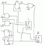
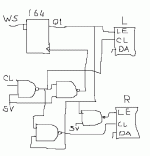
Do they work ?
Big question for me too.
Have to buy a NAND first. All parts shops near me have discontinued.
Can't spice it anymore either. Had Pads, the learning curve of getting used to it is problably a lot longer then self drawing and edging of PCB's
But what do you think of them Rfbrw?
The 2nd simple I2S schematic doesn't work. Realised it when i was bicycling. LE has to be simultane, now it isn't
Bernard posted some comments about the transparancy on female voices with PCM56, i confirmed that too yesterday.
1541 is more to male voice oriented, (again imo because its bipolar transistor-like sound)
Bernard posted some comments about the transparancy on female voices with PCM56, i confirmed that too yesterday.
1541 is more to male voice oriented, (again imo because its bipolar transistor-like sound)
tubee said:
Bernard posted some comments about the transparancy on female voices with PCM56, i confirmed that too yesterday.
That's a little bit mixed up.
On my Sony player with non os mod & 2 x PCM53 changed to instrumentation DAC chips & internal opamps for I/V & S/H & original op amp GIC filter ( 3 x 5534 per channel ) that was designed for 4 x fs but attenuates FS by > 60dB,
femail voices sound even more intimate, closer to the ear, also instruments...
I believe that is caused by the different frequency response of the GIC filter, I have to clone it and try in my DAC.
On the other hand, my DAC seems to be more detailed, likely because of passive I/V.
Unfortunately the op amp I/V in the Instrumentation chips in the Sony player can not be bypassed.
What Sony player and DAC have in common is non os & non TDA chips with very good low level performance.
My DAC at it's current state:
very clean and high resolution ( good low level performance )
transparent & free fom grain ( passive I/V ??? )
free from nervosity ( non os )
tubee said:
Big question for me too.
Have to buy a NAND first. All parts shops near me have discontinued.
Can't spice it anymore either. Had Pads, the learning curve of getting used to it is problably a lot longer then self drawing and edging of PCB's
That's the good thing about a 10 year old simulator. You know where you are with it.
But what do you think of them Rfbrw?
They are more than a little difficult to understand. I can't make out what you are trying to do. I can definitely see no trace of AN207 or any other working schematic I can think of.
Bernhard said:
free from nervosity ( non os )
Someone ought to write a book, " Audiophilespeak for normal people".
rfbrw said:
Someone ought to write a book, " Audiophilespeak for normal people".
In Audiophile press it is usually referred to as glare
- Status
- This old topic is closed. If you want to reopen this topic, contact a moderator using the "Report Post" button.
- Home
- Source & Line
- Digital Line Level
- SAA7210 to PCM56, a Dutch-American connection