Again I am collating some links and references as well to go with my answer, as I want it to be as compherehensive as possible, as I quite often get shot down in flames for some of my views, also the simulations will show the effects of cable length and terminations.
Remember, the 1st thing after the resistive termination is a CMOS Schmitt trigger.
Think about applying signal gain and limiter at the average data level ( AC coupled). This is good because the decision point isn't fixed, it has hysteresis. which means there is significantly more noise and glitch immunity than standard logic gates. see Fig. 4 for the visually inclined
http://www.fairchildsemi.com/an/AN/AN-140.pdf
Last edited:
Sy,
I used HiFace interface with I2S bus as well as for spdif.
That fine product is working good even without mods, comparing to others from same fashion.
The software was installed without any problem for win (standard PC and mac bootcamp win) and mac of course.
I didn't expect this will happened from first try and I was "impressed" a bit, because it is not the usual case. Somehow from that moment I knew that it is very good little device.
.
I opened the unit and find that clock generators are not the same, booth, like it was at the beginning of serial production, for my opp. those was not good as it was? Why they accept that policy I don't know. they put smaller and not accurate like it was when the device launched?
.
I am not sure, I will check it again,
BUT
with win, I2S bus looks like it should be, Latch L/R comes prior one cycle of Sys CLK to the MSB...
At mac osx that is not the case, and Latch is starting the same time, not prior but in sys clk time. That is could results from losing MS bit at the L/R ?
I saw "1" at the place of data bus on the logic analyzer scope, at the place that should be "0", MSB
anyway I am not 100% sure and that should be checked and if so reported.
.
I add own power supply for the module, without using computer PS.
What I found is that spdif output is TTL 5V and insulated with trafo.
I put "P" or "T" network, not sure at the moment, to att. at the right level.
google for
.
Unfortunately device NOT accepting, usb digital isolation at the input, so I add at the output, following by re-clock cir. and after that diff. driver for the cables... (in between I split digital bus from standard L/R into L/L and R/R.
So I made mono I2S diff. outputs as wel as standard.
Judging by the cope there is much, much better signal, when transferred differential line against coaxial.
.
About the I2S bus I tried with coax cables, at first, but I switch to diff. driver
with a adding a resistor in path of I2S bus, I spot much better signal integrity
at the scope. That should be done wit each line because values are not the same... best signal integrity shape i trimmed and replaced with R.
.
cheers
The art of signal integrity is preserving the switching points of the downstream logic on the rising and falling edges of the square wave, and keeping the time interval the same between each change of state, especially for clocks. The rest in not as critical but still important. The ringing stresses the silicon with the extra energy, causing more heat generation, amongst other things. But as long as you keep the switching points clean the wave will be recovered.
The link to the Tektronix app note shows some DDR memory waveforms, and the attached picture shows a snapshot of a real one taken on a 13GHz scope, you can clearly see the high frequency noise from simultaneous switching and SMPS etc causing ground bounce, superimposed on the wave, this is from a 14layer-5 ground plane layout. The right hand image shows some more nice and clean square waves. DDR interfaces tend to be one of the fastest these days and are becoming the memory standard, hence using it as an example. It is laying out these sort of high speed interfaces and seeing them work, that makes me a firm believer in "bits is bits", for the slower frequency interfaces it is even harder to ruin them provides good design practice is followed. Some interfaces have 100-200+MHz clocks, using good engineering practices, layout etc we should be able to sort the lower frequency interfaces used in Audio.
http://www.isotest.es/web/Soporte/F...KTRONIX/DDR/verificacion electrica de DDR.pdf
Qusp,
software a bargain at £16K on top of the base software £20K, luckily work buys me these toys, and pays for the training, which is ongoing as Signal Integrity and high speed logic is back to school and back to basics, physics, and thinking in waves traversing the PCB instead of electrons. Its fun and adding a lot to PCB design, though not making it any easier. Still got a lot of training to do, at the moment I'd say I'm 25% there, but even that gives me a tool and the confidence to release a layout and be pretty certain the signals are going to get from a to b, whereas before it was follow best practice and hope.
Attachments
hey marce, oh indeed, if you are involved in any area related to particle and subparticle states then indeed the research is ongoing. the Bose-Einstein condensate matter-wave experiments and research throws a real curveball.
sounds like you have a pretty fun job. btw most sabre dacs run with pretty fast clock speeds too for mclk, my ackodac and buffalo 2 both run at 100mhz
sounds like you have a pretty fun job. btw most sabre dacs run with pretty fast clock speeds too for mclk, my ackodac and buffalo 2 both run at 100mhz
Hi, Infinia, I think we may be at crossed purposes, I started my post ages before I posted it. The example showns a real square wave (that isn't very square, between the two dots the time interval is 1.284ns), yet the DDR2 interface still works. I was pondering last night whether to do a discourse on changes with measurment and control that I have seen over the years, 4-20mA current loops, the increase in electyrical noise in the envoironment and how most electronics is moveing away from analogue, to mainly digital and digital transmission, with small areas of analogue. I am refering to digital in general, I dont think digital in audio is anything extra special, its digital, just like analogue is analogue to me, I go for 100% perfection in any design I do (I dont achieve it, but still strive for it). I sometimes wonder whetehr sometimes in Audio peiople loos some focus on design and reality, we are not creating an instrument, we are creating some electrical equipement to provide the best possible fidelity in playback of music, speach etc within a tightly defined frequency range.
One of the biggest changes in digital signal transmission has been the change from parallel links, to serial and now because of the advantages low voltage differental signaling, I did VME and G64 motherboards in the late 80s, where all busses were parallel and serial data transmission was the good old RS 232 interface, now once a signal is going off board it will be some form of serial transmission, no more great reals of ribbon cable all over the equipement.
But when it comes to magical effects in digital or analogue I tend to get skeptical, especially when good engineerinig practice (ie I hear its better but have no measurements to show whats happening, head in the clouds brigade) I tend to get cynical...
What I am saying is I do high speed digital, analogue, RF layout every day, whether its audio, communications, video, control or some other aspect of electronics, to me its electronics and should be layed out to the best of both my and the tools I use ability.
Electronic Engineers, well now thats a different kettle of fish
, we are not creating an instrument, we are creating some electrical equipement to provide the best possible fidelity in playback of music, speach etc within a tightly defined frequency range.One of the biggest changes in digital signal transmission has been the change from parallel links, to serial and now because of the advantages low voltage differental signaling, I did VME and G64 motherboards in the late 80s, where all busses were parallel and serial data transmission was the good old RS 232 interface, now once a signal is going off board it will be some form of serial transmission, no more great reals of ribbon cable all over the equipement.
But when it comes to magical effects in digital or analogue I tend to get skeptical, especially when good engineerinig practice (ie I hear its better but have no measurements to show whats happening, head in the clouds brigade) I tend to get cynical...
What I am saying is I do high speed digital, analogue, RF layout every day, whether its audio, communications, video, control or some other aspect of electronics, to me its electronics and should be layed out to the best of both my and the tools I use ability.
Electronic Engineers, well now thats a different kettle of fish
Qusp,
basicly I'm a PCB designer, there are a few of us out there, usualy found in the dark recesses of some office, gibbering away in a corner. !00-200MHz clocks are common these days, look at every PC motherboard. RF is common place and not the dark art it use to be, look at the prolifaration of rf based communication. When you grow up doing such a job, you dont notice wizzy bang developments as you are in the middle of it doing your job, so it dosn't seem so fantastic. The nearest I've done to particles is some work for Daresbury, a firm I worked for did some electronics to control the magnets, and some PCB's for electron microscopes. Again sorry to sound cynical (I am this morning, got a weeks holiday that I thought was gonna be peaceful, and I wake up to a house full of grandkids whove come to stay for a week, with respective mothers etc).
I have been lucky to work on a lot of different projects and products over the years and now do some real fun communications stuff.
I am just getting back to physics with Ralph Morrisons book the field of electronics, I'm an old dog having to re-learn old tricks
i wasnt implying you were involved directly in particle physics, but what i was saying is there are advances and discoveries in that area that will effect all areas including pcb design. from what i gather Acko's day job is high end RF design for both civilian and defense, the 2 fields and their needs are converging as the speed increases.
.As to the accuracy of the simulation software, I use it for all clocks and high speed interfaces such as DDR/Gigabit interfaces and in conjunction with the electrical engineers have checked the results and waveforms using a 13GHz scope.
marce, thanks for the attachments. I have started reading them but I am not engineer and my first post implied that I was looking for practical termination techniques only but then education is good.
13GHz oscilloscope
 ... MAN ! Point your location on world map so I can
  it every morning. I thing by PCB design you mean you design PC motherboards.
From you posts (#16, 17) why to this layman it seems that there is not much difference in square waves with and without termination?
...Audio peiople loos some focus on design and reality
This is the best critique of so called Hi End audio. I am also unable to understand that why adding wood side panel to chassis make their equipment warm sounding...as if it was a violin
.excuse me, Marce in case you missed it in my post, the Schmitt trigger part is already inside the Rx data interface input/s, read up on the data sheet about S/PDIF data input you will see it's not single ended logic levels.
infinia, What does this means for termination? Should I be concerned?
Hi new, not sure what yer Q is?
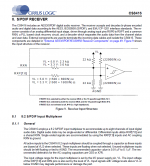
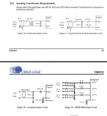
if yer asking does the input of the schmitt trigger affect the impedance of the termination ? see post 27 /attached (figure 9) of sect 8 of the data sheet shows it's a high impedance, so nothing to worry about. Since it is high impedance both the 75R termination resistor and bypass cap need to close to these pins. Ideally the coax connection or controlled 75 ohm transmission line begins or more properly ends at the top of the termination resistor (fig. 18). Simple stuff really.
if yer asking does the input of the schmitt trigger affect the impedance of the termination ? see post 27 /attached (figure 9) of sect 8 of the data sheet shows it's a high impedance, so nothing to worry about. Since it is high impedance both the 75R termination resistor and bypass cap need to close to these pins. Ideally the coax connection or controlled 75 ohm transmission line begins or more properly ends at the top of the termination resistor (fig. 18). Simple stuff really.
Last edited:
From you posts (#16, 17) why to this layman it seems that there is not much difference in square waves with and without termination?
Not the OP but here goes.
Termination is so that the pulse does not see any change at the end of the transmission line to be reflected off. The first edge (rising or falling) sent down a transmission line will look similar with or without termination. The problem is that an unterminated or shorted transmission line will reflect the pulse and that reflected pulse can get mixed up with any subsequent pulses. In the extreme case the reflected signal builds up to such magnitude as to cause insulation failure of the transmission line or receivers. (not the case in audio work) The reason for keeping the lines short is so that they behave more like ideal conductors rather than transmission lines.
To see reflection at work, take a length of pipe open at both ends and bang your hand over either open end, you should both feel and hear a sound wave bouncing back and forth between the open and closed ends, tie a rag around one end and bang the other, the effect should be greatly reduced. The rag forms a crude lossy termination, waves in electrical circuits are very similar in behaviour to their mechanical counterparts.
Hope that helps.
That a good analogy, with the pipe.
Missed the comment about the differences, the un terminated line shows ringing, this is energy that the transmitter has injected into the line that cannot be absorbed by the load, adding parallel termination at the far end will absorb this energy reducing the ringing, it does the same as the cloth Metalsculptor mentioned above. Though this dose attentuate the wave, unless a.c. termination is used (resistor-capacitor).
A good way of seeing what is happening is using a wave tank or similar with a narrow opening at one end. As the ripples (waves) go down the tank some will travel through the smaller opening but some will bounce of the walls then travel back, interfering with the waves travelling down.
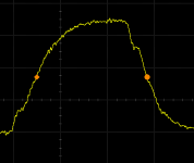
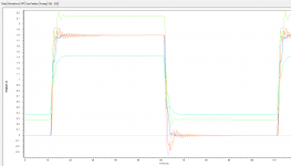
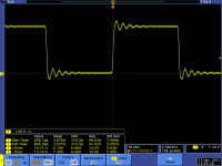
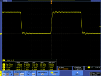
In post #16 the 50mm unterminated line shows no ringing, this is because the wave got there before any returning reflections could interfere with it, whereas the 200mm unterminated line shows the reflections. In #17 both lines are terminated, showing that with the correct termination method, the length of the line can be made almost transparent to the propagating wave (apart from time to travel), as reflections are being absorbed.
Missed the comment about the differences, the un terminated line shows ringing, this is energy that the transmitter has injected into the line that cannot be absorbed by the load, adding parallel termination at the far end will absorb this energy reducing the ringing, it does the same as the cloth Metalsculptor mentioned above. Though this dose attentuate the wave, unless a.c. termination is used (resistor-capacitor).
A good way of seeing what is happening is using a wave tank or similar with a narrow opening at one end. As the ripples (waves) go down the tank some will travel through the smaller opening but some will bounce of the walls then travel back, interfering with the waves travelling down.
In post #16 the 50mm unterminated line shows no ringing, this is because the wave got there before any returning reflections could interfere with it, whereas the 200mm unterminated line shows the reflections. In #17 both lines are terminated, showing that with the correct termination method, the length of the line can be made almost transparent to the propagating wave (apart from time to travel), as reflections are being absorbed.
Irene is still taking toll, electricity is random.
Thanks all for your help!
infinia, what would be the type and value of capacitor used in S/PDIF termination? I saw on Lampizator's website that he uses silver mica capacitor. So this capacitor is in series or across signal to return?
Also, this covers the termination at receiving end. How do we terminated the transmitting end starting from the chip on PCB?
If you need to terminate at the trasmiting end, you would use a series resistor, not paralel termination. This would reduce the ringing and slow the rise time, generaly only one or the other termination schemes are used.
The screen shots show the signal with a 22R resistor and a 100R resistor, the 100R is a better match for the line Zo, there was no reciever termination.
The screen shots show the signal with a 22R resistor and a 100R resistor, the 100R is a better match for the line Zo, there was no reciever termination.
Attachments
- Status
- This old topic is closed. If you want to reopen this topic, contact a moderator using the "Report Post" button.
- Home
- Source & Line
- Digital Line Level
- S/PDIF termination; practical guide?