Yes BS2 stop bands for mid was a problem for ripple in area where mid XOed to tweeter, but maybe it will help going up to 4-5kHz area as XO point. Can try this later, also could be fun see how it looks if woofer and tweeter gets BS2 slopes and mid gets BW4 slopes. XSim is great for this because when sweeping offset up and down then on the fly one can see frq response and transient windows change traces and find best compromise, slopes are made in Rephrase exported as IR-wav file then spl offset in REW and exported as frd-files ready to link to driver inside XSim.
Use Target Function overlay in PCD for Harsch XO
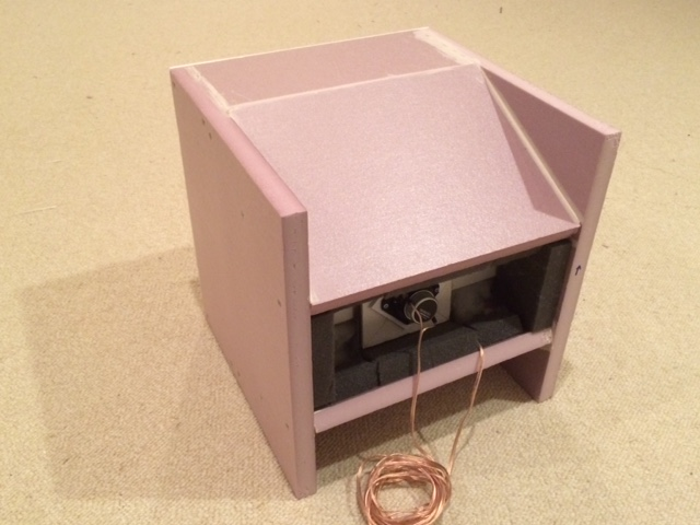
I used Jeff Bagby's PCD to massage the raw FRD data to match the Harsch XO acoustical filter functions. Here is an example with my latest speaker - a tractrix Synergy or Trynergy. This is a hybrid dipole Synergy horn concept that has a nice mix of ambiance and horn directionality. The bass is very impressive going deep while not messing with group delay due to a reflex alignment:
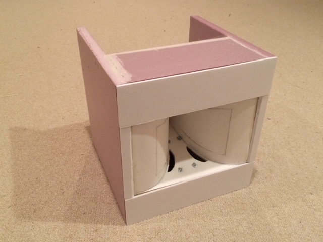
Open back vent:
More info here in this thread: http://www.diyaudio.com/forums/full...l-range-tractrix-synergy-122.html#post4554591
Here is the simulation of the XO function in PCD (the surprsing thing was that it required a BW2 at 500Hz for the LPF and BW1 at 300Hz for HPF):
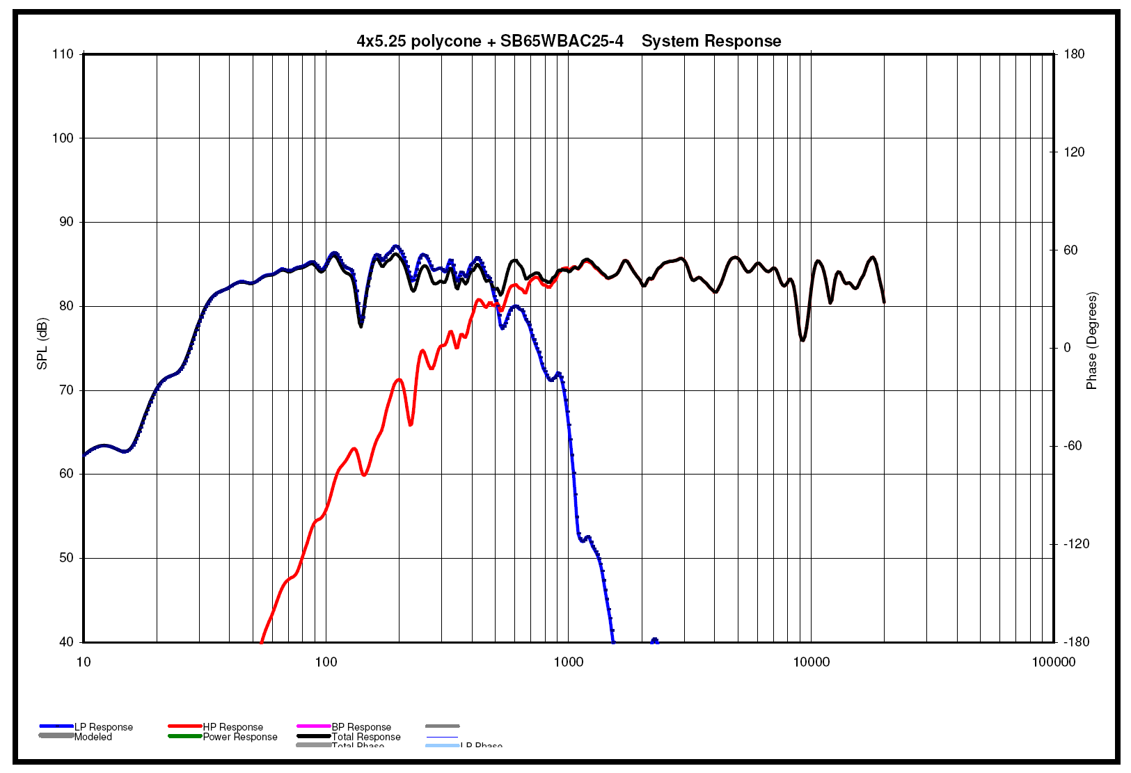
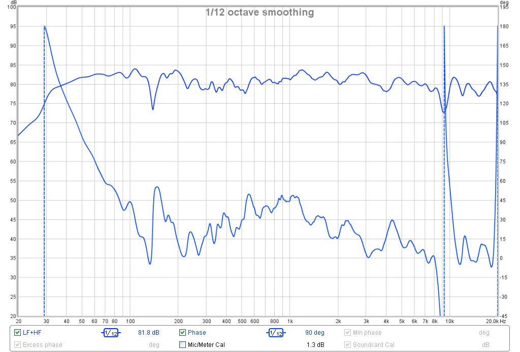
Here is the measured response compared with simulation using PEQ's and electrical XO determined from PCD (no tweaking in real time whatsoever):
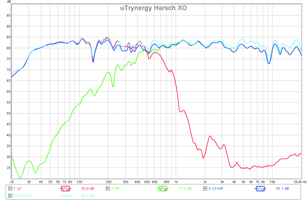
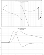
This method allowed me to achieve one of the best phase responses to date for this speaker (+/-25 deg from 200Hz to 8kHz):
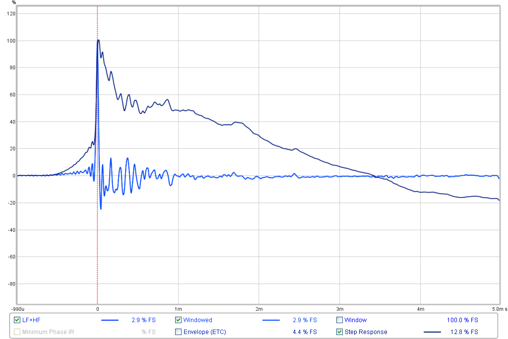
Here is the measured IR and SR, much better than what I had before:
This method was much quicker and more accurate than sitting there and tweaking miniDSP in real time. The key is acquire the FRD files for the woofer, tweeter, and combined in parallel with microphone untouched. It let me determine the acoustic offset to exactly 170mm. This then allowed me to set the delay for Harsch XO much more accurately.
I used Jeff Bagby's PCD to massage the raw FRD data to match the Harsch XO acoustical filter functions. Here is an example with my latest speaker - a tractrix Synergy or Trynergy. This is a hybrid dipole Synergy horn concept that has a nice mix of ambiance and horn directionality. The bass is very impressive going deep while not messing with group delay due to a reflex alignment:
Open back vent:
More info here in this thread: http://www.diyaudio.com/forums/full...l-range-tractrix-synergy-122.html#post4554591
Here is the simulation of the XO function in PCD (the surprsing thing was that it required a BW2 at 500Hz for the LPF and BW1 at 300Hz for HPF):
Here is the measured response compared with simulation using PEQ's and electrical XO determined from PCD (no tweaking in real time whatsoever):
This method allowed me to achieve one of the best phase responses to date for this speaker (+/-25 deg from 200Hz to 8kHz):
Here is the measured IR and SR, much better than what I had before:
This method was much quicker and more accurate than sitting there and tweaking miniDSP in real time. The key is acquire the FRD files for the woofer, tweeter, and combined in parallel with microphone untouched. It let me determine the acoustic offset to exactly 170mm. This then allowed me to set the delay for Harsch XO much more accurately.
Last edited:
Whoah, thanks BYRTT. I was going to try the B&O hole filler at a later stage, great to have the target files. I'll try to get the second non-symmetric Harsch going today.
I also caught a mistake in my previous post, the LR2 is 500 electrical but 700 acoustical. Not the other way around.
I also caught a mistake in my previous post, the LR2 is 500 electrical but 700 acoustical. Not the other way around.
Zonneschimmel,
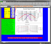
Posted B&O hole filler because you have that nice SS mid and the transient sum of that filter is so nice, so if you don't need too high a SPL level think that filter could be made work for your drivers. For use when you get to that stage later attach a zip folder with two documents by John Kreskovsky, and actual it was that Excel spreadsheet that created frd-files for hole filler XO in previous post. It's not standard slopes so one need target slopes to import to measurement program so the acoustic slopes can be EQed to reach those targets and nice transients, set only two parameters "Fx" and "Gamma" to hit some slopes than can suit ones build as seen below and then use the three grey buttons to create the frd-files.
Also if you ever want to use steeper sloped Duelund filler instead which does turn phase some but as a more strait trace here a link to web calculator http://pro.speakerbuilder.dk/synkron/ to create the frd-files and a pdf document is attached where info about the "A" parameter value is explained.
Have diy fun going HARSH XO today.
Attachments
It's going well using the target curves ")


I did a bunch of measurements for different delays while integrating the woofer, SPL respons looks decent enough across a 10 sample delay window so I have a quick question. When optimising for STEP what is it you optimise for? Best looking triangle shape, cross with zero furthest away, highest peak value at 0, all of the above while keeping pre-rise to a minimum?
I did a bunch of measurements for different delays while integrating the woofer, SPL respons looks decent enough across a 10 sample delay window so I have a quick question. When optimising for STEP what is it you optimise for? Best looking triangle shape, cross with zero furthest away, highest peak value at 0, all of the above while keeping pre-rise to a minimum?
ZSchimmel,
Have you added your woofer to the chain yet? You should be getting a triangle out to at least 3ms or more based on the bass extension you show. Have you checked the polarity If the woofer relative to the amp? The only way to know for sure is use a 1.5v battery andn watch which way cone moves. Sometimes factory polarity is incorrect or amp is inverting. I seem to recall you have a negative going step response of just your woofer. Look at the woofer only step and see if it is positive or negative. If negative, it's not adding to the step you have which looks like tweeter and mid only based on duration of triangle.
Optimize for sharp leading edge well aligned in time with beginning rise of woofer. If you do the overlay on a simulator like PCD or Xsim, it should get the delay very close. My above example I almost got it perfect from PCD - I did not do any manual real time tweaking yet.
Good progress though. You are very close and when you get it - music will play with a snap and bam!
Previous graphs were just for mid-tweet. With woofer best I have gotten is 1.5ms at the moment. If there would be a problem with polarity I assume I would measure a hole with the LR2 crossover and LR2 step shows + for tweet and woofer and - for mid. I haven't touched the wiring in more then a week.
I used the graphical interface for Najda to shape the respons to the target curves. (looks similar but more basic to the minidsp software)
PCD looks perfect but I don't have m$ excell, so pcd is out. I downloaded and tried Xsim but the analogue crossover parts and how to hook them up look quite confusing. I found the highpass and lowpass "blocks" but how to combine 2 2nd order lowpass and with which Q to get a BW4 and translating that info into what I have to enter in the Najda software is an extra step which can introduce errors.
I love measuring and analyzing data but I really really hate fiddling with software so spending an hour measuring different delays is much more fun for me than spending that time figuring out how to translate analogue filters into digital ones
I'm gonna have to learn how to do that eventually but the procrastination is strong in this one..
PCD still uses Excel version 1997 - I'm sure you can find a copy for next to nothing somewhere. Also, I wonder if it translates to Open Office? Definitely a nice program to have in your toolbox if serious with multiway XO's. Has anyone tried PCD on Open Office?
I like playing and measuring too - but after hours and hours of doing that by eye via trial and error with educated guesses - I never was able to achieve anything as nice as my 30 minutes spend on PCD to match the textbook curves. It was surprising that what was needed was a BW1 at 300Hz to achive a BES2 at 500Hz (never would have guessed that via trial and error in real time).
Ok, so no woofer yet - let us know how that goes.
Last edited:
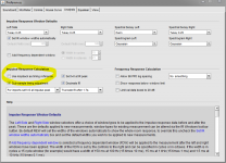
Zonneschimmel if you not on USB microphone but use same soundcard hardware clock for I/O REW can calculate real time of flight between measurement, just don't move microphone position between measurement and its important first EQ/filter LF/MF/HF setion one at a time because when true relative offset is found between sections they must not be EQed selective anymore because that will change their relative timing offset, but system EQ is okay and by that mean EQ that will flow to all three bands at same time doesn't harm and change their relative timing between. See below one of the settings into REW and another is at "Soundcard" tab, use help menu how to create the wire that will help the sync to measure time of flight.
Attachments
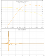
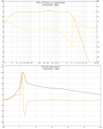
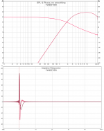
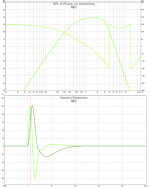
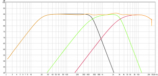
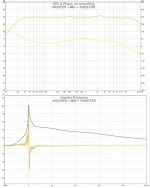
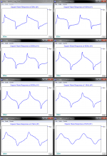
These synthetic visual electric slopes and especially IR/SR plots should could help dial in live system changing settings on the fly into DSP XO.
Pictures:
1 Woofer BW2 20Hz - BW4 500Hz
2 Mid BS2 500Hz - BW4 3kHz
3 Tweeter BS2 3kHz - BW2 20kHz
4 Woofer and mid summed (delay for mid 1,0mS)
5 Mid and tweeter summed (delay for tweeter 0,13mS)
6 System and individual slopes
7 Woofer mid tweeter summed (delay for mid 1,0mS and for tweeter 1,13mS, both delay settings relative to woofer)
Attachments
Last edited:
Wow! Nice work Byrtt - that is indeed really helpful during setup. It's interesting to see that the SR shape can be no better what you have shown here: slight shoulder rise followed by an overshoot peak and the a triangle decay. Just can't get a true right triangle of the same shape as a symmetric 1st order or a B&O hole filler.
My eyes are soon getting 16:10 format if I don't take a break but try more test tomorrow and get back if any works better to get the 3-way as good as two way HARSCH. Was around some fun today that i think you could use for PMC build, did set up a think it was gamma 2,0 hole filler then into REW said A+B to hole filler and tweeter, that created a special slope that also need target curve to be dialed in and think a full ranger could perform it. Why it probably would suit your PMC is because slopes are close to BW1 but when tweeter take filler duty too woofer BW1 can role off little steeper up in octaves where it can have trouble to reach and summing those two weird slopes build upon 3 way or lets say two way with filler : ) they sum with perfect square waves as original Baekgaard hole filler.
Summing hole filler on a plot that reflex on axis is always a pleasure to look at but think HARSCH and other filters with FIR correction have better power response in XO region and less weird lobe. Lately my own FAST had got influenced by Barleywaters advice LR8 and FIR corrected, man it is clean and XO degraded power response running that steep have not much a area width to influence.
Summing hole filler on a plot that reflex on axis is always a pleasure to look at but think HARSCH and other filters with FIR correction have better power response in XO region and less weird lobe. Lately my own FAST had got influenced by Barleywaters advice LR8 and FIR corrected, man it is clean and XO degraded power response running that steep have not much a area width to influence.
Last edited:
Was around some fun today that i think you could use for PMC build, did set up a think it was gamma 2,0 hole filler then into REW said A+B to hole filler and tweeter, that created a special slope that also need target curve to be dialed in and think a full ranger could perform it. Why it probably would suit your PMC is because slopes are close to BW1 but when tweeter take filler duty too woofer BW1 can role off little steeper up in octaves where it can have trouble to reach and summing those two weird slopes build upon 3 way or lets say two way with filler : ) they sum with perfect square waves as original Baekgaard hole filler.
Can you elaborate? You mean my DC130A-8 woofer and DC28F-8 tweeter in the PMC inspired TL can be redone with a BW1 symmetric XO for transient perfect?
http://www.diyaudio.com/forums/multi-way/281778-low-cost-pmc-inspired-tl-monitor-dc130a-dc28f.html
LR8 XO!!! That would indeed need FIR to clean up the messed up phase wraps. Brick wall filter must sound clean though. There has got to be ringing with such as sharp slope though?
Sorry it was not PMC but http://www.diyaudio.com/forums/full-range/280331-fr58ex-ac130f1-micro-fast.html that run BW1 filters will drop a post over there tomorrow to show results, REW closed for today and didn't save session but still have IR-wav files.
IRR LR8 cutoff rings by itself measuring band pass stop bands alone and being same filter effect as cascading 2 times bassreflex : ) but when summed and phase neutralized a FIR filter for me get clean and can't measure artifacts if some care is put into get acoustic slope responses replicate textbook, probably same care as you did put for todays uTrynergy setup. But you right so steep need FIR without that it had not stayed.
IRR LR8 cutoff rings by itself measuring band pass stop bands alone and being same filter effect as cascading 2 times bassreflex : ) but when summed and phase neutralized a FIR filter for me get clean and can't measure artifacts if some care is put into get acoustic slope responses replicate textbook, probably same care as you did put for todays uTrynergy setup. But you right so steep need FIR without that it had not stayed.
It does not, no. PCD needs some MS math engines (I think) that are not available in Open Office. Does not work. And it's quirky in versions of Excel past '97Also, I wonder if it translates to Open Office?
The woofer integration isn't going as smooth as the mid-tweet...
So all following measurements were taken without moving anything. Mic on axis 1m tweeter height. Floor bounce at 3ms looks identical in all measurements.
I used LR2 at 350 for mid and BW4 at 470 for woofer and a little bit of PEQ to get to the target curves
Target curves as measured:

Best step I got so far Woofer positive in Najda 26sample delay (~0.55ms delay) cross with zero at 1.5ms:

Woofer positive 50S delay according to simulations

Woofer negative 50S delay according to simulations

STEP for the above

So the 26s delay setting has the best step but a phase rotation around 500
The 50s delay as simulated has no phase wrap but a crappy STEP
The 50s delay as simulated with woofer polarity reversed has phase wrap and crappy STEP with pre-rise in the wrong direction in comparison to sim
So all following measurements were taken without moving anything. Mic on axis 1m tweeter height. Floor bounce at 3ms looks identical in all measurements.
I used LR2 at 350 for mid and BW4 at 470 for woofer and a little bit of PEQ to get to the target curves
Target curves as measured:
Best step I got so far Woofer positive in Najda 26sample delay (~0.55ms delay) cross with zero at 1.5ms:
Woofer positive 50S delay according to simulations
Woofer negative 50S delay according to simulations
STEP for the above
So the 26s delay setting has the best step but a phase rotation around 500
The 50s delay as simulated has no phase wrap but a crappy STEP
The 50s delay as simulated with woofer polarity reversed has phase wrap and crappy STEP with pre-rise in the wrong direction in comparison to sim
Last edited:

Zonneschimmel, do you use PEQ's to help shape the response to hit the target BYRTT provided?
If you do, try viewing (and correcting) the frequency response in a frequency dependant window:

Try a 4 cycle or maybe 1/6 Width in Octaves. You'll be much more independent from anomalies that occur later in time and it will prevent over correction. Hope it works!
You can view the resulting phase this way too to see what it does before the room has it's way with it. It won't take out the entire room but every bit helps.
If you do, try viewing (and correcting) the frequency response in a frequency dependant window:
Try a 4 cycle or maybe 1/6 Width in Octaves. You'll be much more independent from anomalies that occur later in time and it will prevent over correction. Hope it works!
You can view the resulting phase this way too to see what it does before the room has it's way with it. It won't take out the entire room but every bit helps.
Last edited:
- Home
- Loudspeakers
- Multi-Way
- S. Harsch XO