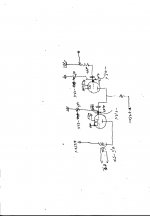
50-60v to 6s17k-v is ok .... no more than 30ma to GS-13 (add miliamp meter to anode and regulate the ma with the negative trimer -1.2 to -2.2v) .... anode can be (maybe better to be ) 140-180 V....negative can be as low as 5V.
Good luck ... it is a very funny project.
regards again
Dimitrios
Good luck ... it is a very funny project.
regards again
Dimitrios
4PSE GS13 GS-13 with 6S53N nuvistor as driver
Hi.
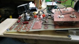
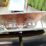
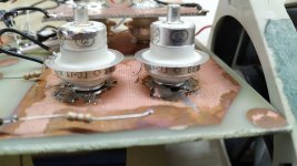
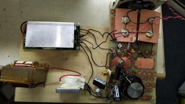
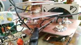
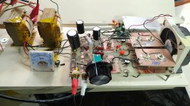
This is the four parallel SE GS-13 GS13 test amp.
The board is home made and constructed for stereo 2PSE GS13 but a test with four PSE is done for curiocity reasons.
The 6S53N has cathode resistor bias. It runs at 60V.
The GS13 fixed bias. It runs at 100-120ma /245V forced air.
The construction as you can see is Manhatan style.
It sounds good. I will upload a live test to You Tube soon.
Regards
Dimitrios
Hi.
This is the four parallel SE GS-13 GS13 test amp.
The board is home made and constructed for stereo 2PSE GS13 but a test with four PSE is done for curiocity reasons.
The 6S53N has cathode resistor bias. It runs at 60V.
The GS13 fixed bias. It runs at 100-120ma /245V forced air.
The construction as you can see is Manhatan style.
It sounds good. I will upload a live test to You Tube soon.
Regards
Dimitrios
Attachments

4PSE GS13 GS-13 with 6S53N nuvistor as driver / GS-13 mounting
hi.
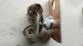
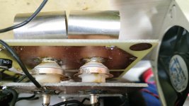
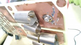
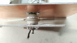
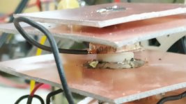
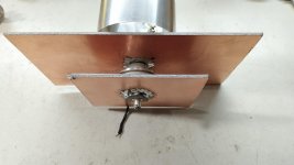
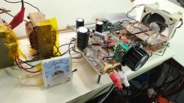
The mounting of the tubes is shown to the pictures.
You can use a dual layer board and open a hole for the cathode and solder it carefuly . the same for the anode plus a curled tin .
Forced air is a must for higher power.
Watch the new test with 4PSE GS13 GS-13 to my You Tube Channel "Dimitris Bel" YouTube
Please Subscribe new videos comming soon
regards
Dimitrios
hi.
The mounting of the tubes is shown to the pictures.
You can use a dual layer board and open a hole for the cathode and solder it carefuly . the same for the anode plus a curled tin .
Forced air is a must for higher power.
Watch the new test with 4PSE GS13 GS-13 to my You Tube Channel "Dimitris Bel" YouTube
Please Subscribe new videos comming soon
regards
Dimitrios
Attachments
-
 IMG_20200309_110646.jpg595.5 KB · Views: 269
 -
 IMG_20200309_110626.jpg430.8 KB · Views: 253
 -
 IMG_20200309_111028.jpg573.3 KB · Views: 160
 -
 IMG_20200309_105643.jpg540.4 KB · Views: 162
 -
 IMG_20200309_105559.jpg493.1 KB · Views: 146
 -
 IMG_20200309_110721.jpg374.6 KB · Views: 120
 -
 IMG_20200309_111045.jpg373.4 KB · Views: 139
 -
 IMG_20200309_110732.jpg542.9 KB · Views: 202
Last edited:
Thank you very much. Looks very interestingThe schematic... UHF russian ceramic 6S17K-V and GS13 GS-13 audio SE amp
GS-13 mounting
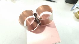
It is a very simple way to have cooler to all small ceramic russian tubes.
As cooler I use mainly the copper of a dual layer board and additional tin to the anode with a 12V PC fan at 6.3V(very silent).
Without cooler it is not possible to use them full power.
Theese tubes are very strong made and survive soldering. But it must be done carefully and slowly not to overheat.
Testing without fan they overheat and melt the solder. Even after that they continue working.
The latest test with 4PSE GS13 audio amp works for hours without any issue at 120ma 245V.
GS-13 is 13W disipation and at 120ma (the four) is about 30W disipation. Way under the limit of 52W.
To this amp I use 6S53N as driver(at 60V) with the same cooling system.
I do not expected to play so good. You can watch it here --YouTube
Any comments are welcommed
regards
Dimitrios
Attachments
Last edited:
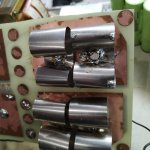
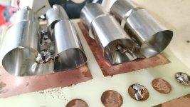
GS-14 GS14 and GS-4 GS4 mounting new style
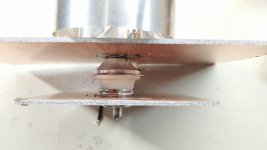
Hi this a new style mounting for ceramic russian tubes .
1.It is a GS14 GS-14 (the one with the round tin) tested for audio amp. It does not operates as it sould for audio. At 245V and -2.2V to the grid it draws only 35ma. Trying to increase the current the grid voltage increases to 0V and the sound destroyed.
2.It is a GS4 GS-4 which is almost equivalent to GS-13 ..... At 245V and -2V to the grid it draws 40ma and sounds good...it sounds good but I think GS-13 is a little bit better.
Regards
Dimitrios
Attachments
Last edited:

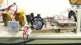
Hi!! Happy New Year 2022.... I have made some improvements to the project 2XParallel Single Ended Rusian Ceramic GS13 GS-13 triode tube with 6S53N Russian Nuvistor Triode as driver in stereo.
Its almost final.
The final contitions are :
220V 35ma each for the GS13 , with fix negative to screen bias,
and 50V for the 6S53N nuvistor with cathode resisnance bias .
It works well .......
Its almost final.
The final contitions are :
220V 35ma each for the GS13 , with fix negative to screen bias,
and 50V for the 6S53N nuvistor with cathode resisnance bias .
It works well .......
Attachments
If you need any quesstions or any help ask ....Thankyou for the update. I have bought some GS13s and will start working on them when it gets cooler.
ray
- Home
- Amplifiers
- Tubes / Valves
- Russian UHF amplifier tubes