Is there a rotary device that can be used to control an input interface that has +/- switches on a board?
For example, an FM tuner board that has + and - (momentary) switches for tuning. Instead of using push button switches, I would like to use a rotary device like a tuning knob to control the frequency selection for this board. Ideally, this would be a device with three terminals: +, - and GND. When the knob is turned clockwise, it should momentarily short + and GND, once per some degree of rotation, say 30 degrees. When the knob is turned counterclockwise, it should momentarily short - and GND, once per the same degree of rotation.
Is there a device like this, or do I need to build one using a rotary encoder and some logic?
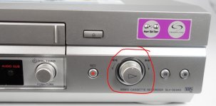
They exist in some form. For example the old Sony SLV-SE840 type VCR has something similar although with an additional 'push switch' action as well. The rotation on these was minimal though, perhaps 5 degrees either way, with a very definite click action and centre return. What the actual switch on the panel was like physically though I can't say.
Attachments
You mean like a data wheel? You turn it continually until the number get there?
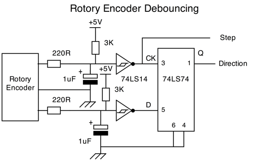
I have turned rotary encoders into up and down buttons for foot use. Never went the other way, but the logic is basic. You'd need two bits in quadrature, then use one for pulsing and the other for direction.
But it would be helpful to see the relevant part of the schematic.
I have turned rotary encoders into up and down buttons for foot use. Never went the other way, but the logic is basic. You'd need two bits in quadrature, then use one for pulsing and the other for direction.
But it would be helpful to see the relevant part of the schematic.
You meen something like this:
https://www.google.ro/search?q=rota...ved=0ahUKEwjV7YqY8c7RAhUsD8AKHckEC1cQ_AUIBigB
https://www.google.ro/search?q=rota...ved=0ahUKEwjV7YqY8c7RAhUsD8AKHckEC1cQ_AUIBigB
Edit: Perhaps I should ehm.. Not comment before reading.. 
There's thing called rotary encoders. They're basically like the digital signal a soft knob on a receiver gives out. Binary positions. That is then translated into a certain action by a microcontroller. It can be switching a certain array of relays according to the binary position/combo of the rotary encoder.
There's thing called rotary encoders. They're basically like the digital signal a soft knob on a receiver gives out. Binary positions. That is then translated into a certain action by a microcontroller. It can be switching a certain array of relays according to the binary position/combo of the rotary encoder.
You have step and direction, but you still need to logic that into the two switch inputs in the unit. The unit is not set up for driectin and pulse, it is currently set up for a pulse input for each direction separately. hence the desire to see a schematic.
You may or may not need a debounce. The unit input circuits are no doubt already debounced for the up/down switches in it.
You may or may not need a debounce. The unit input circuits are no doubt already debounced for the up/down switches in it.
- Status
- This old topic is closed. If you want to reopen this topic, contact a moderator using the "Report Post" button.
- Home
- Design & Build
- Parts
- Rotary device to replace +/- switches