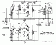
Ian, while we have you here, could you please have a look at the picture below and let me know if you have any idea what the circled part is? It's not in the schematic and it was originally also there in my Cadet. (When I overhauled it it I got rid of it and it works fine without it.)
Which pin numbers of which tube (type and ideally usage) was it connected to?
Which pin numbers of which tube (type and ideally usage) was it connected to?
If my memory (refreshed by the image) serves well, it was pins 6 and 9 of one of each pair of the output valves. In other words, it connected the anodes of the triode and pentode "part" of the valve, as per the edit of the schematic I have uploaded below (although I must admit that I cannot remember if it was V1 or V2 of each channel).
When I was repairing my Cadet, I'd assumed this was a resistor someone added for feedback. I measured it without removing it and replaced it with the value I thought it was (I have since decided all this was wrong). This resulted in an ever increasing feedback noise, so I took them out again.
When I measured the part out of the circuit later (you'd have thought that I'd have been wise enough to do this to begin with), I couldn't get any resistance measurements and the capacitance test also didn't give anything, at any of the ranges my multimeter has. As you can kind of see from the photo, the component is shaped like an "orange drop" capacitor, is a kind of olive green to brown colour and has colour code on it (which in my case was barely legible as the amp I'd bought was old, not well looked after and filthy).
Attachments
Last edited:
Well I can tell you what the part is - it is a capacitor, very low value. These sort of caps are generally 100pF or less.
As to what it is doing - My first opinion is that it is there for stability. C4 is very large in comparison and R12 is reasonably low value so in effect this added cap is effectively increasing the Miller capacitance at the grid of the pentode. That will be the dominant pole of the amplifier. So it is "slugging" the dominant pole to keep the amp stable at high frequencies. It is unusual to slug just one side of the push pull BUT I'm not 100% convinced that this is what happens. The concertina phase splitter is very dependent upon equal loading on the anode and cathode sides. It may well be that this cap added on the anode side will also affect the drive on the cathode side.
You can get a good gauge of wether it is needed or not by looking at square wave response into a resistive load on an oscilloscope. Add caps (start with about 10pF) to get rid of any ringing at the square wave edges. If there is no ringing then the caps are not required.
Cheers,
Ian
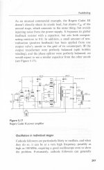
Very interesting, this schematic also features the 24uF values for the C8 and C9 electrolytics, as seen in my as well as OP's Rogers. I guess there were a few variations in the six/seven years it was made...
Thanks for this Cookj, I'll add them back in - saves me from having to borrow an oscilloscope and do the test Ian suggested.
Thanks for this Cookj, I'll add them back in - saves me from having to borrow an oscilloscope and do the test Ian suggested.
Have just read this item and in past experience have found resistors break down also as I had one in my cadet 3 control unit (r16) in one channel, so replaced all anode and cathode resistors inc. caps (for 25v) as it was in pieces (I think it made a sound improvement, but was it my imagination) next time will do some feq. gen. with oscilloscope checks first
- Status
- This old topic is closed. If you want to reopen this topic, contact a moderator using the "Report Post" button.
- Home
- Amplifiers
- Tubes / Valves
- Rogers Cadet 3 Problem

