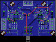
I copied Prasi's P88 PCB and added some goodies:
1. Jumpers for shorting input stage feedback resistor - easy way to select 0dB gain or whatever gain is selected for the input stage
2. There is no footprint for ALPS RK27 pot in the Eagle libraries so I just left enough room on the pcb to accommodate it's footprint 28mm x 26mm and added three solderpads that suit ALPS RK27 pin layout
3. Input cap footprint is like Prasi's 15mm lead spacing but I added footprint for 22,5mm output film cap because there is 10uF Wima polyester cap in the local shop with that footprint
I think this is not finished pcb design. This pcb has more potential for improvement.
Attachments
Last edited:
You can find plenty of RK27 libraries around (here's one for example: EAGLE Parts) if you want2. There is no footprint for ALPS RK27 pot in the Eagle libraries so I just left enough room on the pcb to accommodate it's footprint 28mm x 26mm and added three solderpads that suit ALPS RK27 pin layout
")
DIYmodules.org - Free EAGLE Libraries, Tools for Electronics Designers another eagle library site where preview is available that helps a lot and search engine works rather well. but not an exhaustive collection.
The PCB in post #61 has some issues. I would suggest to revert all traces to the top layer as much as possible with solid ground plane on the bottom layer as Prasi did it initially. Another problem to look at is the mixing of power supply return and signal ground routes. I would suggest to route the power supply from the middle of the PCB to the corresponding power pins of the op-amps under the ICs (between the rows of pins), then route everything signal related on the outer (left, right) sides of the PCB making sure that signal traces do not cross power supply traces. Such arrangement will prevent mixing power supply return and signal ground routes.
Regards,
Oleg
Regards,
Oleg
That could be done only if one would use one dual opamp per left/right input stage and one dual per left/right output stage, as I did in my actual P88 from the photo. But the attractive side of Prasi's board is that each channel has it's own dual opamp - there is no crosstalk between channels! Everything is crammed inside duals and there is crosstalk if left right is inside one opamp. That's why JRC developed MUSE series of high performance opamps, to solve, as much as possible, the problem of the crosstalk inside dual opamps.
Last edited:
obviously i have less knowledge than most on here, but: if there's no crosstalk between the two channels, wouldn't there be crosstalk within the channel? Meaning, the channel would "talk to itself" because both amplifier stages are inside the same opamp? ....just a thought.
ivan, your pcb layout looks fantastic - but i think you should include a balance pot
ivan, your pcb layout looks fantastic - but i think you should include a balance pot
obviously i have less knowledge than most on here, but: if there's no crosstalk between the two channels, wouldn't there be crosstalk within the channel? Meaning, the channel would "talk to itself" because both amplifier stages are inside the same opamp? ....just a thought.
ivan, your pcb layout looks fantastic - but i think you should include a balance pot
If chanel talk to itself the name for that is -Crazy chanel-...

Hi Mixi,
It is nice to see you very active on the forum too ... and I'm glad you like the pcbs!
I had to make a break due to moving and never-ending renovation and now I'm slowly coming back to my hobby
As for the PCB layout and channels cross talk. If you look at the OPA2134 datasheet Fig. 12 as an example, you'll see that the channel separation is better than 120dB up to 20kHz and better than 110dB up to 100kHz. I find it more than enough for line level audio applications. I think significantly higher cross talk can be generated by the PCB layout constraints.
It is nice to see you very active on the forum too
... and I'm glad you like the pcbs!I had to make a break due to moving and never-ending renovation and now I'm slowly coming back to my hobby
As for the PCB layout and channels cross talk. If you look at the OPA2134 datasheet Fig. 12 as an example, you'll see that the channel separation is better than 120dB up to 20kHz and better than 110dB up to 100kHz. I find it more than enough for line level audio applications. I think significantly higher cross talk can be generated by the PCB layout constraints.
I really can not explain why its happening, probably due to the actual resistor values.. do you have a schema of your actual build?
Lack of balance pot should not affect gain.
As per ESP site, the first stage has gain of 6, followed by a loss of 3 dB in balance and second stage gain of 6.02= total of 9.02.
regards
Prasi
So i measured all the resistor values and they are all well within spec (1% metal).
I measured both stages independently and they each have again of exactly 2x.
As soon as i connect the stages (with a jumper or today i used a 50k pot) the first stage looses some gain. The signal of the first stage will then only be amplified 1.77x while the second stage keeps the gain of 2x.
It seems like the gain of the first stage is reduced by connecting it to the second stage. It's not really a problem as I'd still have enough gain but I'd really like to understand why this is happening
Again, I setup my circuit exactly according to the schematics on the ESP Site.
I use a +/-15 VDC dual supply.
Oleg,
It would be very difficult to route pcb the way you suggested with the component placement Prasi used. PCB would need a completely new layout of components. I just liked Prasi's layout and accepted some limitations that comes with it. But I followed your recommendation and moved most of the tracks to top layer leaving just necessary tracks on the bottom.
It would be very difficult to route pcb the way you suggested with the component placement Prasi used. PCB would need a completely new layout of components. I just liked Prasi's layout and accepted some limitations that comes with it. But I followed your recommendation and moved most of the tracks to top layer leaving just necessary tracks on the bottom.
So i measured all the resistor values and they are all well within spec (1% metal).
I measured both stages independently and they each have again of exactly 2x.
As soon as i connect the stages (with a jumper or today i used a 50k pot) the first stage looses some gain. The signal of the first stage will then only be amplified 1.77x while the second stage keeps the gain of 2x.
It seems like the gain of the first stage is reduced by connecting it to the second stage. It's not really a problem as I'd still have enough gain but I'd really like to understand why this is happening
Again, I setup my circuit exactly according to the schematics on the ESP Site.
I use a +/-15 VDC dual supply.
can you try setting up a 100R at the output of first stage instead of 1k5 and ALSO instead of 15k to ground, a 100k to ground like Ivan's schematic?
regards
Prasi
At the output of first opamp stage you should have 50-100R series resistor, than 10K log pot and 100K input resistor to ground at the input of second opamp stage.
Hello Ivan,
Are you sure you mean to use 10k pot and then a 100k resistor to ground at the input of second op-amp?
Esp, in better vol control recommends a ratio of about 8 (RVol/R-loading)
ESP - A Better Volume Control
the example given in esp uses 100k lin pot and 12k loading resistor.
regards
Prasi
ESP preamps are all with fake log pot, they use 100k linear pot and 15k resistor from wiper to ground. That's different from my schematic which is standard issue with log pot. ESP fake log pot is very good for it gives somewhat better tracking between channels than standard log pots, but I never use fake log pots because they are too loud at the beginning of the pot movement. It does not suit my high efficiency loudspeakers.
Last edited:
- Home
- Source & Line
- Analog Line Level
- Rod Elliot Project 88 question