Hi Guys,
I've been wading through the various P3A threads doing my research before building some P3A pcbs from Rod.
My question is regarding the best silicon choices. It seems like all of the most recommended driver transistors are no longer available.
Rod recommends the MJE15034 and MJE15035 however it has been stated that these can be a bit harsh. The recommended other option of the BD139-140 has also been suggested as sub par on these forums.
Are there any other currently available driver transistors that can be recommended?
If not, then presumably the 15034 and 15035 would be the better option?
Output transistors: it seems like the 2SA1943 & 2SC5200 are the best option and these are available from mouser. Are there any other readily available options that I should be considering?
People tend to overlook the MJE243/253 as drivers. They are better than BD139/140 for this job. KSC2690/KSA1220 are also good if you can get them.
2SC5200/2SA1943 are good *IF* they are genuine, but you're getting them from Mouser so I wouldnt worry about that. It looks like they are selling the OnSemi (ex Fairchild) versions which are good.
If you're buying from Mouser, get the KSA1381 and use this for the VAS transistor Q4.
2SC5200/2SA1943 are good *IF* they are genuine, but you're getting them from Mouser so I wouldnt worry about that. It looks like they are selling the OnSemi (ex Fairchild) versions which are good.
If you're buying from Mouser, get the KSA1381 and use this for the VAS transistor Q4.
hello, in the prototype I put together for high school, I used BC546 for the differential pair, BD139 / BD140 for the VAS and drivers, MJL 21193/4 for the outputs.
I put a little heatsink on Q4, although using it at + -35V was not necessary, but it is already ready for + -42V.
for the next layout, i am going to use MJE 15032/3 for drivers, BD140 for the VAS, MJL 21193/4 for output, and +-42V power supply.
I put a little heatsink on Q4, although using it at + -35V was not necessary, but it is already ready for + -42V.
for the next layout, i am going to use MJE 15032/3 for drivers, BD140 for the VAS, MJL 21193/4 for output, and +-42V power supply.
My question is regarding the best silicon choices. It seems like all of the most recommended driver transistors are no longer available.
Rod recommends the MJE15034 and MJE15035 however it has been stated that these can be a bit harsh. The recommended other option of the BD139-140 has also been suggested as sub par on these forums.
If this is your first P3a build, I'd suggest to build it using the components called for on Rod's secure site BOM. You can then tweak later and have a baseline to compare to.
Keep in mind the P3a is not an ultra-low distortion amplifier. It colors the sound as some would put it. You can therefore view the specified devices as intentional choices to arrive at it's signature sonic characteristics.
Has anyone actually bought these from Mouser, because it looks like they only stock the KSA1381 and the KSC3503 in different hfe-gradesIf you're buying from Mouser, get the KSA1381 and use this for the VAS transistor Q4.

Probably not the end of the world if it's true, but annoying nonetheless...
I made my P3A with own PCB ( largely inspired by SAKIS's comments and pictures - thanks to him and Rod of course).
drivers : BD139 - BD140
output : MJL4281 - MJL4302
Very very very pleased with the result.
I also used those driver and output devices, along with KSA1381 for the VAS and KSC1845 for the input pair. Be aware these have a different pinout, but actually fit quite easily with a rotation of the pair as the emitters are connected together. Only reason I used those over BC546's was I had a pair that was closely matched.
Started with MJE15034 and MJE15035 as the drivers, and as others have said I thought it was a bit harsh. Much preferred the BD139 and BD140.
Hi All,
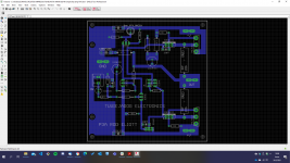
I just thought that I could also use some critiquing on my lay-out
1st image, highlighted, current source ground goes to the star ground, zobel ground is tapped direct on the power ground.
2nd image, current source ground goes direct to power ground, zobel ground is tapped to the star ground.
3rd image, a cheap shot how does it look like when assembled (not tested yet
If my memory serves, I have read that the current source ground should be separated from the rest, also by placing a common heatsink for the drivers and the bias servo should improve thermal tracking (just like John Bali did in his version) not on my version. Another question, I have seen lay-outs that uses ground lifter (10ohms) but others do not have it. Is this necessary or is this just a matter of preference?, I understand this is CFP. Anyway is there something that I should worry about in my current lay-out?
Best Regards!
Hi sir
Mi 2sc5200 base emitter 220 ohm burn what will fault.please help me thanks.
this is an another variant...
Not a good design, the bias transistor should be in thermal contact with one of the drivers. All explained here.
TTC5200/TTA1943 variants are the cheapest TO264 (large) style transistors available. Toshiba's Japanese production includes several updated variants with different product numbers in the common TO3P-N size. Check their current catalog: Transistors | Products | Toshiba Electronic Devices & Storage Corporation | Asia-English.....
Are there any other currently available driver transistors that can be recommended?
If not, then presumably the 15034 and 15035 would be the better option?.......
Onsemi produce several variants of MJL3281/MJL1302 in those styles too and any will be fine with the nod going first to these higher current types in the large TO264/TO3P-L case which are a tad more rugged (and expensive!). That's the case style Rod illustrates and lists in his recommendations.
If you aren't pushing the power levels at maximum recommend supply voltage and using 4-6R speakers, the Toshiba semis should be fine too but either way, buy from bonafide distributors so you don't get fakes.
The BD139/140 drivers are fine but the OP (Sakis, East Electronics) preferred an obsolete pair of original Philips drivers (BD829/830, IIRC). They aren't just the same devices in different packages either but the important matter is that tinkering with parts before you even know what the original design sounds like leaves you in doubt and maybe disappointment anyway. Might I suggest that you aren't going to reach nirvana with the first guess so try the other types later, when you come to realise the sound quality most people here are describing as great.
p3a
ok, I understand what you suggest, but it can be easily solved, 3 cables are soldered to the board and the transistor is placed near one of the drivers, anyway I am going to modify that, although I tell you that in the last year of the school we have assembled this design and it worked without problems, the future design will have the drivers set at 90 degrees with respect to the current one, with an aluminum plate the 3 transistors will be thermally connected, rod on its page says that you do NOT have to mount the bias transistor on the main heatsink, that works well in my design, but the drivers do not heat up either, so it can be considered optional ... I have not had problems of that type so far ...
Not a good design, the bias transistor should be in thermal contact with one of the drivers. All explained here.
ok, I understand what you suggest, but it can be easily solved, 3 cables are soldered to the board and the transistor is placed near one of the drivers, anyway I am going to modify that, although I tell you that in the last year of the school we have assembled this design and it worked without problems, the future design will have the drivers set at 90 degrees with respect to the current one, with an aluminum plate the 3 transistors will be thermally connected, rod on its page says that you do NOT have to mount the bias transistor on the main heatsink, that works well in my design, but the drivers do not heat up either, so it can be considered optional ... I have not had problems of that type so far ...
The first version I have assembled of this amplifier, only had problems with noise from GND when turning off the equipment, it had no problems with the bias adjustment, which if it is very critical, is to use a preset of several turns, the one of only one back is quite uncomfortable to adjust ...
In addition to what IAN says, the a1943 c5200 devices in digikey I found them as a manufacturer farchild, it would be another correct variant when building, with respect to the drivers, in my first version I used bd139 / 140 without any problem
REEDIT: farchild was acquired by ONSEMI lol
REEDIT: farchild was acquired by ONSEMI lol
Last edited:
- Home
- Amplifiers
- Solid State
- Rod Elliot P3A Layout - Critics