Is there a sub for RFP18N10? In a punch 150 amp?
Not sure never looked, start a new thread on the subject so we are not going back and forth on two different subjects in the same thread. Thanx!!!
Ok Perry now that I am able to lock a waveform on my scope where do I test the input on this amp with the probe as to compare it to the output to see if the weak output channel is as least clean output? When testing the output do I just put the probe on the + terminal of the outputs with the amp powered on and a signal of some sort present??
The input at the RCA jacks (disconnect the RCA jacks and check the signal on the center conductor if it's not clean when it's plugged in).
For the output, you'll check it on the bridging speaker terminals.
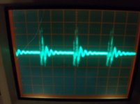
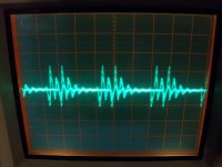
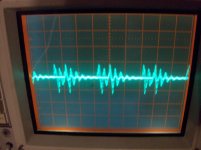
Ok Perry this is what I have come up with the first pic is the input.
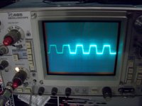
The second pic is of the output of the channel without the problem.
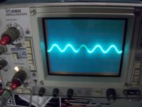
The third pic is of the output of the channel with the problem.
I used the radio with no antenna from my head unit so just consistent static and had the volume very low on 1. Everything looks clean to me but I am not the expert. You can clearly see the lower output on the 3rd pic vs the second. I checked them on the bridging terminals. What do you think??
Attachments
Well I dont have a sine wave generator so I guess this amp will have to be put on hold. Can you point me in the direction of a cheap unit or a used one on ebay or something? I just dont know what I am looking for. Any suggestions would be great. Thanks again Perry................
Do you have a head unit with a CD player (preferred to the others here), an MP3 player or a computer with a sound card? Any of those will produce a sine wave. The following is a 100Hz test tone.
http://www.bcae1.com/temp/100hz300seconds.zip
http://www.bcae1.com/temp/100hz300seconds.zip
Do you have a head unit with a CD player (preferred to the others here), an MP3 player or a computer with a sound card? Any of those will produce a sine wave. The following is a 100Hz test tone.
http://www.bcae1.com/temp/100hz300seconds.zip
Thanks Perry got it downloaded and burned to a disc. I will put it in the head unit and post the results, just wondering how much volume I should use????
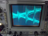
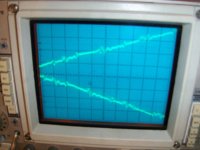
Hello Perry first pic is input and second two pics are of output. Scope settings were 50m vol/div and 5us time delay those were the best setting. I also really had to increase the intensity to be able to see the wave form. Let me know what you think............Thanks as always
Attachments
Sean, didnt know that 100ix would kick your butt so bad! LOL. Sorry man, hope you get it figured out!
Most of the time they dont but now that Perry has taught me how to use my scope I think I will kit its butt..................LOL
Set the timebase to 2ms and the vertical amp to 5v/div. Adjust the gains/input so that the output swings to about ±3 divisions. Tweak the timebase so that you get about 3-4 full cycles on displayed.
The scope is set to the settings you requested except the time base.
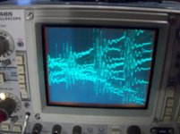
Both pics are of output. The square wave is the strong channel and the wavey form is the weaker channel. If i increase the volume the weaker channel will produce a square wave form and matches the other channel. I tried messing with the gains as they are at maximum setting. If I try and back them off the baseline returns to a straight line and does nothing, can't get the scope to trigger. I adjusted the time base to 5ms in order to get more cycles I could only get 2 cycles on the 2ms setting. Let me know what you think.....
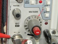
OK. That's not 5v/div. That's 50v/div. I'm assuming that your probe is set to 10x. With these probes, the indicator lamp for the 10x position will not light up because they're missing the pin to tell the scope to change to the other indicator.
The left channel is clipping.
Set the input/gain level so that the strong channel is at the threshold of clipping.
Are the signals the same level at the base of Q110 and Q210?
If you're looking at the signal with the scope, you'll have to adjust the vertical amplifier setting. If nothing else, confirm that the signal is clean on the bases of those transistors with the scope. Measure the AC voltage on those points with your multimeter.
Are the gains set to the same point (max, preferable)?
OK. That's not 5v/div. That's 50v/div. I'm assuming that your probe is set to 10x. With these probes, the indicator lamp for the 10x position will not light up because they're missing the pin to tell the scope to change to the other indicator.
The left channel is clipping.
Set the input/gain level so that the strong channel is at the threshold of clipping.
Are the signals the same level at the base of Q110 and Q210?
If you're looking at the signal with the scope, you'll have to adjust the vertical amplifier setting. If nothing else, confirm that the signal is clean on the bases of those transistors with the scope. Measure the AC voltage on those points with your multimeter.
Are the gains set to the same point (max, preferable)?
The probe is on 10x so I need to set it to 1x?
Not sure out of the 5 pins on Q110 and Q210 is the base??
Yes the gains are set to max
I use them at 10x because the load on the circuit is 1/10 of the load when set to 1x. Just be aware that the indicator does not indicate the correct voltage. If you short between the BNC connector and the metal ring on the scope connector as shown below, you'll see the other indicator lamp light up. Those are the vertical amp settings when using the probe at 10x.
What are the markings on the transistor?
What are the markings on the transistor?
Attachments
- Status
- This old topic is closed. If you want to reopen this topic, contact a moderator using the "Report Post" button.
- Home
- General Interest
- Car Audio
- Rockford Punch 100ix