the internet connection where i work is down so i have to go up two flights of stairs to post and i cannot remember everything.
After some examination of the auxiliary voltages, (Perry was right) i managed to get things a bit straight.
I noticed that whenever i touched R312 the noise went away for a second and after re-soldering R312 much of the noise was gone.
I can -sometimes- completely eliminate the noise for just a sec if i turn up and down the gain pot. But it always comes back again.
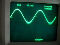
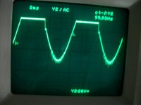
Now, the high frequency noise is still present, but at least the amp produces audio at the output with signal fed to the RCAs. However, it sounds distorted.
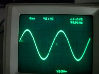
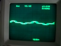
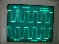
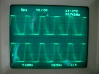
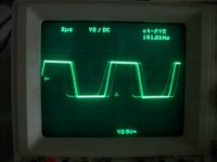
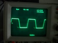
Here is what i mean (amp if fed with 100Hz sine)
Pic 1 the signal between C355 and R300
pic 2 pin 1 of U300
pic 3 the output of the amp at low volume
pic 4 the output of the amp at a bit higher volume....
thats why it sounds distorted
After some examination of the auxiliary voltages, (Perry was right) i managed to get things a bit straight.
I noticed that whenever i touched R312 the noise went away for a second and after re-soldering R312 much of the noise was gone.
I can -sometimes- completely eliminate the noise for just a sec if i turn up and down the gain pot. But it always comes back again.
Now, the high frequency noise is still present, but at least the amp produces audio at the output with signal fed to the RCAs. However, it sounds distorted.
Here is what i mean (amp if fed with 100Hz sine)
Pic 1 the signal between C355 and R300
pic 2 pin 1 of U300
pic 3 the output of the amp at low volume
pic 4 the output of the amp at a bit higher volume....
thats why it sounds distorted
Attachments
All the above op-amps have -6V at pins 4 and 6V at pins 8.
Assuming that you mean pins 2/3 and 5/6, here is what i have referenced to gnd with no signal into the amp
U300
pin 1 0.039
pin 2 0.007
pin 3 0.005
pin 5 0.003
pin 6 0.008
pin 7 0.007
U301
pin 1 0.027
pin 2 0.075
pin 3 0.073
pin 5 0.073
pin 6 0.031
pin 7 0.18
U302
pin 1 -0.021
pin 2 0.007
pin 3 0.007
pin 5 -0.007
pin 6 -0.022
pin 7 0.31
if i inject signal to the RCAs, at C355/R300 i get 0.045VDC and around -0.45VDC at the output (it grows in relation to the output swing).
I'm not familiar with that scope so I wanted to confirm, especially since you only mentioned the 0.45v of offset. It could have been that you were using a probe that didn't match the scope so it would display the wrong vertical amp settings. This is a common problem.
Do the voltages change on the op-amps when you drive it hard enough to force it to 15v of offset?
Does the subsonic filter make a difference (in reducing the offset)?
Do the voltages change on the op-amps when you drive it hard enough to force it to 15v of offset?
Does the subsonic filter make a difference (in reducing the offset)?
ok, set gain high so the amp has around -15VDC of offset (the offset is negative)
here is what i get at the op-amps
(+/-6V is present on pins 4 and 8)
U300
pin 1 0.182
pin 2 0.177
pin 3 0.003
pin 5 0.182
pin 6 0.170
pin 7 0.170
U301
pin 1 2.364
pin 2 -2.465
pin 3 0.004
pin 5 -0.005
pin 6 2.364
pin 7 -1.377
U302
pin 1 -2.232
pin 2 0.068
pin 3 0.005
pin 5 -0.012
pin 6 -2.20
pin 7 2.645
the subsonic does not affect the offset
pin 2 of U304 has around -0.17 at all times.
Last edited:
This part of the circuit seems to be working as it should but it may require a few more tests using two probes to monitor two points in the circuit simultaneously.
Post the waveform that you have on the center leg of Q430 and the 3rd leg of Q431. Set the scope to DC coupling, 50v/div and set the timebase so that you have 3-4 complete cycles.
Post the waveform that you have on the center leg of Q430 and the 3rd leg of Q431. Set the scope to DC coupling, 50v/div and set the timebase so that you have 3-4 complete cycles.
my scope at the current set up is only rated for 20V/div so i have set it to 5V/div and both probes are set to x10.
first pic is at lower gain, and the second one is at higher (with more than 20VDC offset at the output).
first pic is at lower gain, and the second one is at higher (with more than 20VDC offset at the output).
Attachments
- Status
- This old topic is closed. If you want to reopen this topic, contact a moderator using the "Report Post" button.
- Home
- General Interest
- Car Audio
- Rockford Fosgate T30001bd