i know this may seem like a stupid question, but what should my meter be set to value wise(obviously ohms but which), my meter is a bluepoint eedm503a, and i have a centech(junk). my values on the blue-point are i guess diode check(|<-), a dot with what looks like sound waves, 200,2k,20k,200k,2m,20m.
i seem to get different readings from the same components, i guess from a shorted component in the line. on one i will get like .700, then the other .160.
thanks
i seem to get different readings from the same components, i guess from a shorted component in the line. on one i will get like .700, then the other .160.
thanks
alright here is all my measurements. measured on outside legs while still on board. going right to left
75344g measured @ 200 input side
1---0
2---0
3---0
4---0
5---0
6---0
7---0
8---0
9---0
10---0
11---0
12---0
lm317t measured @200k input side
1--7.1
2--3.7
lm337t measured @200k input side
1--.2
2--.2
28n15 measured @2k output side
1--.001
2--.113
3--.113
4--.112
5--.111
6--.111
7--0
8--0
9--0
10--0
11--0
12--0
36p15 measured @ 200 output side
1--158
2--21.6
3--148
4--146
5--146
6--146
7---0
8---0
9---0
10---0
11---0
12---0
thats all my measurements minus the components i have already removed and ordered replacements.
i kept having to switch the measuring value to get a reading.
thanks
Last edited:
well from what i have been reading, i can test to see if the mosfets and transistors r any good using a dmm on ohms. thats what i was doing, i didnt put the black probe and red probe on any certain foot besides outside feet.
if i am doing something wrong here please let me know.
if i am doing something wrong here please let me know.
You need to check them with the black on one leg and the red on another leg.
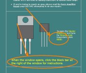
On the following page, go to the bipolar transistor section and open the link indicated in the attached image. This section is for bipolar transistors but the lead placement is the same when checking either type of transistor initially.
Basic Amplifier Repair - Transistor Test Applet Link
Post the values (or screencaps of the form with the values) for one power supply FET, the first 28n you listed and the second 36p you listed.
Which FETs have you removed from the MEHSA insulators?
Attachments
i have already remove the (4) u1620's from not only the mesha boards but the from the amp its self, and tested them outside amp, and still they appear bad. and basically from what your article says all my readings that are 0 are bad, and some of the items reading an actual resistance may still be bad?
Last edited:
Listen to perry hes the man here.
The quickest way to test the output transistors (FQA28N15-FQA36P15) is to place black meter probe on leg 1 (right leg) and red probe on middle leg. Then black probe on leg1 and red probe on leg 3 then finally black probe on middle leg and red probe on the 3rd leg. You should read nothing near 0 ohms.
If you arent sure if its defective or not pot your results as followed
Leg1-2:
Leg1-3:
Leg2-3:
Do this with all outputs and all power supply fets.
alright, did all the testing.
on the output side i set my meter to the 200 ohm range. went from right to left on amp testing the 28n15's and 36p15's.
doing it in order described i got.
first the 28n15's
1--.2-1.3-1.3 !!!!
2--40/115/76
3--40/115/76
4--40/115/76
5--40/115/76
6--40/115/76
on seven through 12 got a no reading meter on any of the legs
now the 36p15's
1--53-148-96
2--53-148-96
3--53-149/95
4--53-149-96
5--53-149-96
6--53-149-96
also on these on the last six got a no reading on meter on ANY of the legs
this was the output side
now for the input/power side i got a no reading on everything on any legs.
Never use NTE parts they are usually very expensive and they tend do do more harm then good in amps.
I think this is what your looking for:
MUR1620CTG ON Semiconductor Rectifiers
I think this is what your looking for:
MUR1620CTG ON Semiconductor Rectifiers
alright retested...after cutting legs off shorted one
first are the 28n15 measured @ 200k
1--155/0/82
2--140/0/84
3--130/0/96
4--117/0/105
5--111/0/10
6--163/0/95
7--153/0/96
8--153/0/101
9--136/0/105
10--129/0/111
11--124/0/116
second are the 36p15 measured @ 200 range on meter
1--53/115/95
2--.4/21/21
3--54/149/96
4--54/149/96
5--54/149/96
6--54/149/96
7--0
8--0
9--0
10--0
11--0
12--0
no readings on any legs on last six
next are from the power side of the amp
the lm317t's measured @ 20k
1--7.2/7/.1
2--5/5/.1
now the lm337t @20k
1--17/.2/4
2--13/.2/13
thanks
There are MUR1620CTRGs and MUR1620CTGs. Probably 2 of each.
so there is a difference between the two of them? lol i had no idea.
- Status
- This old topic is closed. If you want to reopen this topic, contact a moderator using the "Report Post" button.
- Home
- General Interest
- Car Audio
- rockford fosgate t15002 amp troubles