I have an issue with a 2006 RF T10001BD. It has the red PCB. I've looked through a couple of the other threads on here and some have similar issues, but I've checked for those things. The amp originally had a blown PS section. That has been fixed and appears to have no issue. I can get clean output from the amp, but only for about 1-2 minutes. After that, R50 burns up. Even with no signal in the amp, R50 burns up. This means that something on the +6V line is drawing excess current, even though the amp functions during this time.
Right now, when operational, R50 drops about 3V across it, which leads to a ~280mA current through that resistor. This makes it burn ~750mW in a 1206 250mW resistor. I can see why it only lasts a couple minutes") I know it will be asked about the voltages on Q201, so:
I know it will be asked about the voltages on Q201, so:
Base: 6.75V
Collector: 17.5V (Voltage on other side of R50 is 20.4V)
Emitter: 6.05V
All of that looks good. I tried pulling both R213 and R210. The drop across R50 dropped to about .6V (~60mA... 40mW), with obviously no output from the amp. Obvious suspect is one of the three opamps after R213. I reinstalled R213 and R210 and measured the drop across R213. That drop was 0.7V (67mA). What I don't get is why the current through R50 grows so much. Is there somewhere in the schematic that I am missing that the +6V goes to? Any thoughts or ideas?
Right now, when operational, R50 drops about 3V across it, which leads to a ~280mA current through that resistor. This makes it burn ~750mW in a 1206 250mW resistor. I can see why it only lasts a couple minutes
I know it will be asked about the voltages on Q201, so:Base: 6.75V
Collector: 17.5V (Voltage on other side of R50 is 20.4V)
Emitter: 6.05V
All of that looks good. I tried pulling both R213 and R210. The drop across R50 dropped to about .6V (~60mA... 40mW), with obviously no output from the amp. Obvious suspect is one of the three opamps after R213. I reinstalled R213 and R210 and measured the drop across R213. That drop was 0.7V (67mA). What I don't get is why the current through R50 grows so much. Is there somewhere in the schematic that I am missing that the +6V goes to? Any thoughts or ideas?
Attachments
Monitor the temperature of all of the op-amps and any other ICs being supplied from that regulator. Are any getting hotter than expected?
Capacitors can cause increasing current but that generally only happens when a capacitor is installed backwards. Check the capacitors on the output of that regulator as well to see if any are getting hot.
You can install a larger through-hole resistor in place of the SMD resistor to give you more time to find the fault. If you have a small 12v lamp (like an 1156), you can probably use that in place of the resistor as a current limiter like you would in the B+ supply.
Monitor the temperature of all of the op-amps and any other ICs being supplied from that regulator. Are any getting hotter than expected?
Capacitors can cause increasing current but that generally only happens when a capacitor is installed backwards. Check the capacitors on the output of that regulator as well to see if any are getting hot.
You can install a larger through-hole resistor in place of the SMD resistor to give you more time to find the fault. If you have a small 12v lamp (like an 1156), you can probably use that in place of the resistor as a current limiter like you would in the B+ supply.
In the 30 seconds to a minute I dared leave the amp on, the only thing that got scorching hot was R50. I will try the idea of putting a higher power through hole resistor in to mitigate the heat temporarily.
I removed C201 and tried it again with no change. When it was removed, I also measured C201, and it came in good at 10.6uF. When I had R213 removed, I also pulled C216 and it measured at 10.5uF. I did not try to run the amp with C216 removed and R213 installed, but I figured if it measured OK out of circuit, it should be OK in circuit. Do you know anything else that runs off the +6V? From what I see, it is U1, (Solid +6.1 at its VCC pin), U2, U200, U203, and a couple places where it is going through larger (1k+) resistors.
Does the voltage drop across/current through R213 seem reasonable or high? To me, 60mA going to 3 different opamps doesn't sound unreasonable depending on the opamp.
Try freezing all of the components fed from the 6v line so that they all have a blanket of ice crystals on them, then power up the amp. Does one melt the ice faster than the others?
Use a can of compressed air/gas inverted if you don't have any component cooler spray.
I don't think 60ma is too much but I've never really checked it on one of these amps. I'd think that it would be about the same as the current through the negative regulator. You can compare the voltage across
Did you check C29?
How does the temperature of Q201 compare to Q202?
Try freezing all of the components fed from the 6v line so that they all have a blanket of ice crystals on them, then power up the amp. Does one melt the ice faster than the others?
Use a can of compressed air/gas inverted if you don't have any component cooler spray.
I don't think 60ma is too much but I've never really checked it on one of these amps. I'd think that it would be about the same as the current through the negative regulator. You can compare the voltage across
Did you check C29?
How does the temperature of Q201 compare to Q202?
I will try to find some spray, in the mean time I have more information. It looks like they did do some updates between 2004 (schematic I have) and 2006 (schematic I just got). The 10V and 10V gate on the 2004 are fed by a separate LDO. On the 2006, the 10V are generated AFTER R50 through a circuit similar to Q201. Removing R200 drops the voltage across R50 to 1.2V (115mA, 138mW). The 10V signal only goes to the gate drivers. I have tested both caps C63 and C62 out of circuit and they appear to be good. With C63 or C62 in or out, the gate drivers pull ~170mA of current (through R200, 1ohm).
But then... I did something dumb. I was checking out some of the other output drivers, and I forgot to reinstall one. When I turned it on, it popped two of the output FET's. So.... I need to go fix that before I get back to the +6V problem
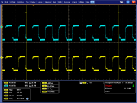
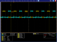
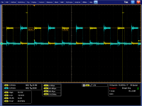
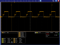
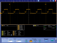
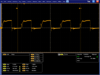
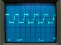
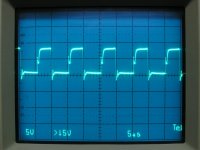
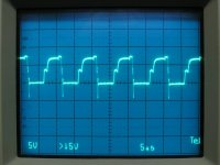
OK... back after getting some parts replaced. All audio outputs are replaced, all drivers replaced, and the LM5110 gate drivers (U5 and U11) and all 3 LM6172 opamps that ran off the 6V. No change in my +6V overcurrent situation, but I think I have another issue. The gate signals going to the output FET's looked fishy, so I traced it back to the transformer. Here are pictures of the transformer output side right after the diodes. All of the diodes measure good. Is this a case of a bad transformer? One of them only goes to 10V, which is what the U5 gate driver puts out. I assume this transformer is a step up? The last two plots are the gate drivers before the transformer. Those look good to me. Any other ideas on what might be causing this? I am hoping it is not the transformer as I don't know of a source to get a new one
Attachments
Last edited:
To determine if the drive signal is good, you need to check across the gate and source for each of the FETs with the scope in differential mode. This will allow better resolution because all drive signals will be visible with the scope set to 5v/div.
I assume you are talking about the output FET's? The third and fourth pictures I have up are connected directly to the base of the driver transistors Q203, Q206 and Q215, Q218 respectively. The first two pictures go to what looks like the driver's driver (Q204 and Q217)
. If you do not have the schematic, I can send it to you.I have the diagram.
The only definitive way to determine that there is a good drive signal is to measure directly across the transistor terminals. This has to be done using the scope in differential mode.
I took the plots for each transistor, then I forgot the flash drive in the scope
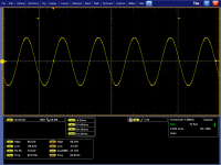
I will post them up later. They looked... so so. I know that isn't descriptive without pictures. For the heck of it, I ran an audio signal through the amp with no load and I got a clean sine wave out of the speaker outputs of up to 130V pk-pk before clipping. I had to keep a 5 ohm 1W resistor in place of R50, but it was stable for 20 minutes before i shut it off. With that resistor in place of R50, I had the same current draw through the resistor, but it was a stable current draw. I checked all of the component IC's to see if any were getting hot, but none seemed too bad. U2 was warm, but it wasn't running away. Most of the IC's on the output side of the board have been replaced anyway. So I am still at a loss for what is causing R50 to pull so much current through it. I will post up the gate pictures later when I get back to the lab.
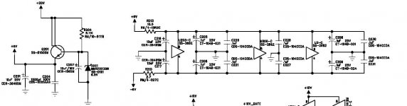
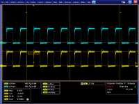
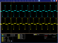
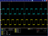
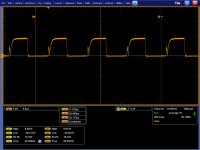
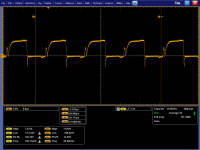
Here are the FET gate signals. The math function was used for channel 1 (gate) - channel 2 (source) to produce differential mode. The ground clips for each probe were connected to the negative terminal. The pictures start at Q207 and go up to Q214 in order. The last plot is the output of the amp at the speaker output at 60Hz with no load. This is with a larger power handling R50. No components powered after R50 seemed abnormally warm. Thoughts?
Attachments
-
 Output with larger R50.png73.2 KB · Views: 58
 -
 Q214 Gate.png91.9 KB · Views: 46
 -
 Q213 Gate.png73.4 KB · Views: 50
 -
 Q212 Gate.png90.7 KB · Views: 53
 -
 Q211 Gate.png75.2 KB · Views: 144
 -
 Q210 Gate.png71.9 KB · Views: 146
 -
 Q209 Gate.png75.3 KB · Views: 138
 -
 Q208 Gate.png75.7 KB · Views: 147
 -
 Q207 Gate.png72.4 KB · Views: 144
What model Tek are you using? It appears to be one of the $10k+ scopes.
I took the following from another T1000-1bd. Although they are not identical, the corresponding signals are similar enough to make it appear that your amp is OK.
If you want to determine why R50 is overheating, you'll have to follow all circuits connected to it. If Q201 and Q202 are approximately the same temperature, the current must be flowing through another branch. The +14v_gate circuit or something that it feeds may be the next place to search. I think you already checked C29, if not, check it.
Attachments

Last edited:
What model Tek are you using? It appears to be one of the $10k+ scopes.
I took the following from another T1000-1bd. Although they are not identical, the corresponding signals are similar enough to make it appear that your amp is OK.
If you want to determine why R50 is overheating, you'll have to follow all circuits connected to it. If Q201 and Q202 are approximately the same temperature, the current must be flowing through another branch. The +14v_gate circuit or something that it feeds may be the next place to search. I think you already checked C29, if not, check it.
It is a higher end tek. It is a DPO7104. I am an engineer at an aerospace company. I am allowed to use the equipment after hours. I design RF (radio frequency) power amplifiers, and I do other electronic repair as a hobby to keep my non-work based electronics skills sharp (or at least not dull
).I am pretty sure I checked C29, but I will recheck. It is easy to remove and test. I saw the 14V gate circuit also. The regulator part of that circuit seemed fine. The 1 ohm R200 shows about a 0.17V drop across it when operating, so ~170mA is going through it. That is all that appears to be running off that +14V gate signal/regulator. The +10V regulated voltage only runs U5 and U11 from my investigation. U5 and U11 pulling 170mA average doesn't seem so bad considering they are up to 5A FET drivers. I have replaced U5 and U11 anyway though, so I doubt they are the problem. Current draw through R200 was the same before and after replacement of U5 and U11. So the combination of ~80mA through R213 (~70mW) and ~170mA (170mW) through R200 adds up to basically the limit of R50's power handling. Something else seems to be drawing power away somewhere, but I certainly can't seem to find it. U1 seems to be rock solid at +6V, so I'm guessing that isn't sucking down too much power or I would see some voltage sag. Everything else that runs off the +6V line is fed through 1k+ resistors that I have measured OK.
If you have a T10001bd laying around there, can you tell me what voltage drop/current through you have on R50, R213, and R200?
You can be pretty confident that I won't tell you that you need a better scope.
I found one here but it uses the other driver ICs (2004 model).
R50 = 0.601
R200 = 0.131
R213 = 0.297
Thanks for the reference voltages.
I'm glad I don't need to use a better scope.
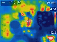
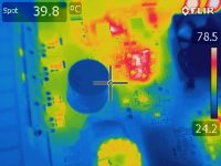
We do have a DPO72054 in the lab, but it is a pain to use non-50 Ohm probes. The adapters required are cumbersome to say the least I did happen to find today that we have one other piece of equipment that more or less instantly solved at least a chunk of the puzzle. I used a FLIR thermal camera to finally try and pinpoint this once and for all. Lo and behold... C211 was a big bright red spot about 50 degrees higher than anything else. I pulled it, and the draw through R213 dropped to right about 0.3V (as referenced by you above). The draw through R50 is still too high (2.5V drop vs 3V before), but getting closer.
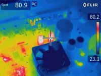
I also noticed that D211 was scorching hot (125 deg C!) under the FLIR. I don't have that part on hand, so it is on order now. Any thoughts if that would be causing the gate drivers to draw more current? The actual zener voltage seems not-completely-failed at 9V but I will replace it either way. There is some excess power dissipation in there somewhere. Hopefully it is just the D211 part itself and not something else.
One step closer...
Last edited:
I don't know if D211 is a problem. You could replace it with a leaded 8.2v Zener to see if there were any changes. That would prevent you from having to wait and find that it's not a problem.
I run into the same problem with a leaded zener as opposed to the the SOT-23 version... I don't think I have an 8.2V on hand
. I do get your point though that the leaded one will have a higher power handling to see if that helps out my current draw. I did try to pull C241 and run without that since it is part of the D211 circuitry, but the amp did not like that too much. It drew more current with it out, so I put it back in. I have the amp current limited to 4A right now, so it shouldn't have damaged anything else. C241 also tested OK out of the circuit.I've used up almost all the tricks in my book otherwise. We will see if I can find anything else.
I got D211 replaced. It still runs hot, and I replaced C241 right next to it also. So I'm guessing that isn't an issue. Couple FLIR pictures for reference are attached below. Next step is to actually power a real load and see what happens. I need to go find a PS that will do over 10A though... I'm sure there is one around here somewhere
Only things that run hot are a couple resistors, the discrete regulators, and D211. These were all with no load or input. Current draw was about 3A @ 13.5VDC. That seems decent based on some other rockfords I've worked on.
Only things that run hot are a couple resistors, the discrete regulators, and D211. These were all with no load or input. Current draw was about 3A @ 13.5VDC. That seems decent based on some other rockfords I've worked on.
Attachments
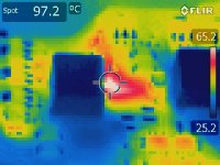
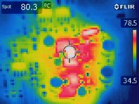
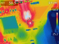
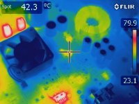
It looks like Q17/18 are very hot. Does replacing the 0 ohm resistor R169 with a 4.7 ohm 2w resistor (or something close) help to keep R50, and Q17/18 cooler without affecting the output voltage of Q17/18?
I will try that. With putting a 4.7 Ohm instead of a 0, are you just thinking it might spread some of the voltage drop/power dissipation around so it isn't all happening in the regulator? I didn't really think much about Q17/Q18 being out of whack because Q201/Q202 look to go to about the same temp of ~80C. Also, based on the voltage drop across R200 between what I have and the references you gave me for the 2004 model you had, the numbers come out roughly the same. I would expect this to be true even with the differences in IC's. Both the 2004 and 2006 IC's are just FET drivers, so the majority of the current/power going to U5 and U11 should be what's actually driving the output circuitry, not the supply/bias current of U5 and U11 themselves. I could be wrong on that, but it made sense at the time when I thought about it.
- Status
- This old topic is closed. If you want to reopen this topic, contact a moderator using the "Report Post" button.
- Home
- General Interest
- Car Audio
- Rockford Fosgate T10001BD Issue