Hello, received this amp for repair and it was a mess.
All the P/S fets were blown to pieces, the gates were fried, the drivers were melted.
I repaired the supply and it produces a nice square wave, idles fine, and is stable.....but it wouldnt shut off even with the remote unhooked.
I found U4 one of the LM339D's defective and melted. I replaced it and the amp now powers up and down as it should.
4 of the outputs were blown to bits, I soldered new ones to the MESHA board and I am getting ready to install them to the main board.
My question is do I need to replace the other 4 to have matching date codes? I am unsure which fets are used if in parallel and didnt know if the class D needed to have matching outputs as in all 8.
I replaced the 4 pictured but not the other 4 still attatched to the board.
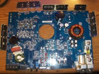
1st pic= main board
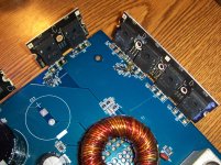
2nd pic= repaired power supply
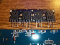
3rd pic= newly soldered outputs
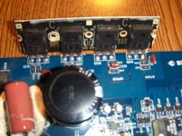
4th pic= exisiting outputs
Thoughts anyone?
All the P/S fets were blown to pieces, the gates were fried, the drivers were melted.
I repaired the supply and it produces a nice square wave, idles fine, and is stable.....but it wouldnt shut off even with the remote unhooked.
I found U4 one of the LM339D's defective and melted. I replaced it and the amp now powers up and down as it should.
4 of the outputs were blown to bits, I soldered new ones to the MESHA board and I am getting ready to install them to the main board.
My question is do I need to replace the other 4 to have matching date codes? I am unsure which fets are used if in parallel and didnt know if the class D needed to have matching outputs as in all 8.
I replaced the 4 pictured but not the other 4 still attatched to the board.
1st pic= main board
2nd pic= repaired power supply
3rd pic= newly soldered outputs
4th pic= exisiting outputs
Thoughts anyone?
Attachments
The amp powered up fine with the exisiting 4 fets after replacing the blown ones and installing them to the main board the amp clicks and draws massive current.
I think the drivers may be blown Q216=A56 Q215=A56 Q218=A06
Which are the drivers and which is the regulator?
Should I replace them all?
I think the drivers may be blown Q216=A56 Q215=A56 Q218=A06
Which are the drivers and which is the regulator?
Should I replace them all?
You may need to remove the drivers to check them definitively. There are some low value resistors connected across some of their terminals. If Q216 has failed, also check Q217.
The regulators are Q210 and Q202.
You can replace all of them if you have them. I think you should check the ones you pull of anyway so that you will know which ones have failed. That could help if it heeds further troubleshooting.
The regulators are Q210 and Q202.
You can replace all of them if you have them. I think you should check the ones you pull of anyway so that you will know which ones have failed. That could help if it heeds further troubleshooting.
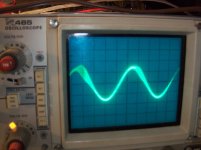
The amp has output but it is distorted.
1st pic is at low volume and hooked to a speaker sounds fine.
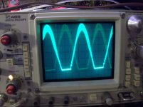
2nd pic is increased volume and sounds distorted hooked to the sub.
100Hz signal scope settings were 2ms/10vd
The sub sonic switch make no difference, nor do any of the pots or switches.
Maybe something in the protection circuit?
2004 model board # PC-5445-C
1st pic is at low volume and hooked to a speaker sounds fine.
2nd pic is increased volume and sounds distorted hooked to the sub.
100Hz signal scope settings were 2ms/10vd
The sub sonic switch make no difference, nor do any of the pots or switches.
Maybe something in the protection circuit?
2004 model board # PC-5445-C
Yes the drains 2 divisions above and the sources 2 devisions below...but............
I think the problem lies in the area I replaced the fets in because the drain of Q210 and Q207 are 2 divisons above the reference line on their drains with no signal on their source, and Q208 and Q209 are 2 divisions below the reference line on their sources with no signal on the drain. These are the fets I did not replace.
The fets I replaced Q213 and Q212 are 2 divisions above the reference line on their drains with a signal on their sources as well, Q214 and Q211 are 2 divisions below the reference line on their sources with a signal on their drains as well. The 4 fets have the same signal on the leg they are not suppose as compared to the other 4.
I hope all of this makes sense and is just not confusing things.
All of the tested fets have a nice square wave but the extra signal showing where it shouldnt be in the 4 fets I replaced looks like this......
Attachments
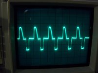
So why do the other fets I checked 2 of them have a signal on the drain and 2 of them have a signal on the source, but the 4 I replaced have signal on the drain and source of each fet?
All the signals I checked were a nice square wave except for this extra one I posted a pic of??
All the signals I checked were a nice square wave except for this extra one I posted a pic of??
I replaced Q216, Q218, Q215 but in being in a little of a hurry to remove them I pried to hard and broke them so was not able to test them.
I am not sure which was defective. I metered a few smd resistors but all in the circuit of course and didnt find anything strange except for R250 is a 2.7 ohm and meters at 5.50M ohms seems wrong but was not sure if it was because it was in the circuit.
Maybe I should remove it and re-test?
I am not sure which was defective. I metered a few smd resistors but all in the circuit of course and didnt find anything strange except for R250 is a 2.7 ohm and meters at 5.50M ohms seems wrong but was not sure if it was because it was in the circuit.
Maybe I should remove it and re-test?
- Status
- This old topic is closed. If you want to reopen this topic, contact a moderator using the "Report Post" button.
- Home
- General Interest
- Car Audio
- Rockford Fosgate T10001