Hello I have a Rockford Fosgate power 1000 classic amplifier that needs repair
When a signal is applied there is no sound from the outputs unless The source input is turned up high I will hear loud crackling from any channel . I did some test as per another thread that Perry Babin was assisting with troubleshooting .
Here is what I have
secrets is online now secrets United States
diyAudio Member
Join Date: Sep 2011
input voltage 13.8v (car battery and charger)
45.9+
45.3-
op regulated shield pin 4 and 8 each is 14.5+and 15.1-
7918 #1
pin1 00.6v
pin2 -23.1v
pin3 -17.4v
7818 #2
pin1 25.5v
pin2 0.03v
pin3 18.2v
diodes 5.38 one way #2
5.93 one way #2
black probe on tab of 7818 test 7918
pin 1 0.00
pin 2 23.2v
pin 3 18.00v
diodes 17.5 v at stripe end on both
striped end read 0 ohms to pin 1 of the 7818
Any other ideas or instructions on what to test next ?
Thanks fellas.
Report Post
Attachments
Read page 73 of the car audio site (link below). Read ALL of it but read the 'best initial settings' at least twice.
On the schematic diagram, there is a voltage source labeled -17 sw. Confirm that that voltage is present on one leg of the 4.3k resistor in the audio circuit for each channel.
To follow the signal if the -17v is present...
The initial setting the the vertical amplifier will probably be about 1v.
Start probing at the back of the RCA jack where the center conductor goes into the board to confirm that you have a clean signal.
Then probe the output pins of all of the preamp op-amps to see which have signal. Set the switch to 4 channel input. Set the gains at max.
Correction, you're looking for ±17v. More below.
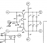
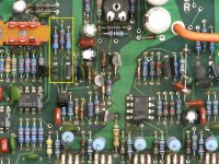
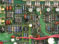
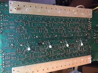
Image 1 is the ±17v regulator circuit. I can't find it on the photos I have.
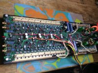
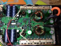
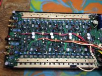
Image 2 and 3 are the differential amplifiers. There are two 51.1 ohm resistors that connect between two transistors and the 4.3k resistor. Confirm that you have +17 on one 4.3k resistor and -17v on the other 4.3k resistor. All 4 channels will likely be the same but find the groups for all channels and confirm.
Schematic is below photos.
Image 1 is the ±17v regulator circuit. I can't find it on the photos I have.
Image 2 and 3 are the differential amplifiers. There are two 51.1 ohm resistors that connect between two transistors and the 4.3k resistor. Confirm that you have +17 on one 4.3k resistor and -17v on the other 4.3k resistor. All 4 channels will likely be the same but find the groups for all channels and confirm.
Schematic is below photos.
Attachments
- Home
- General Interest
- Car Audio
- Rockford Fosgate Power 1000 problem