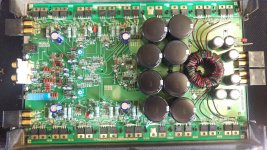
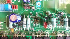
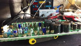
OK, so I received this amp today. Someone had it out at a garage sale, claimed it worked. ?? I received it an opened the cover to visually inspect the board and components before I just b+ the amp. It is very old, and condition is eh. any ideas on the burnt resistors and spot on the board if it's visible in the picture.
any ideas on the burnt resistors and spot on the board if it's visible in the picture.Attachments
i think i can handle most or all of this? it is a lot of time, testing all of those smd's, no scope, the rails and resistors i can handle. even the smd, just go through and test all the burnt ones or corner to corner? All of them. Where should i start, If i choose that route?
Desolder one leg of all remaining source resistors and the gate leg of all audio FETs.
Measure the resistance of all of the SMD resistors connected to the gates and source resistors. Mark all (red sharpie) that appear out of tolerance.
The most important thing is not to do any damage. If you damage the pads, it will make it harder to repair and will make it much more expensive to have it repaired if you cannot repair it.
those resistors are 0.1Ohm and 5% tolerance, are they 1watt or 2? ill also need to order the driver transistors MPN A06, A56, just correct me if i am wrong anywhere perry please. What audio FETs output transisors should i use? There are a few in here, IRF938D, IRF964, IRF640
Outputs are supposed to be IRF640s and IRF9640s.
You'll need to order the drivers and all of the various SMD parts.
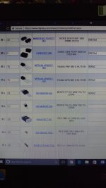
Attached is a layout of a similar amp. The layout is slightly different but I think the designations are the same. Plan on replacing all highlighted plus any that you find out of tolerance.
The source resistors are 2 watt.
You'll need to order the drivers and all of the various SMD parts.
Attached is a layout of a similar amp. The layout is slightly different but I think the designations are the same. Plan on replacing all highlighted plus any that you find out of tolerance.
The source resistors are 2 watt.
Attachments
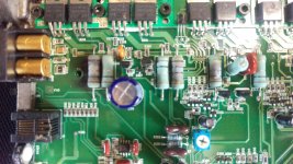
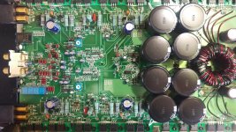
Most of the audio transistors were either badly repaired or heated so badly they were almost separated from the rail already. So I lifted all of them being ill replace all of them anyway. Most of the and I tested even the burnt ones are still within tolerance.this is where I'm at.
Attachments
I would also recommend the non-N version of the output transistors.
You don't need 0.5% tolerance 20k resistors. They are likely more expensive.
Punch vs power is minimal but may be 12dB vs 24dB crossovers and similar features. I'm sure that others here could be more specific.
You wrote:
Most of the and I tested even the burnt ones are still within tolerance.
Something is missing.
I was writing i tested most of the SMD Resistors and a few are out, ill be replacing all on the sheet you sent me just for good measure anyway. Thanks everyone for the help on the parts, i ordered the correct ones today. I 'll just return the other ones, the .5 will work ok thought, It just means they are more accurate correct? it will only be +-.5? If so i may just use and keep them, i think they were way more expensive.
The tighter tolerance is OK. When ordering parts, it's good to get extras. Tight tolerance parts may prevent you (or anyone) from ordering extras (plenty of extras for cheap parts).
Shipping will likely be more than it's worth to return the parts. The IRF640N is used in some class D amps so they be useful later.
Shipping will likely be more than it's worth to return the parts. The IRF640N is used in some class D amps so they be useful later.
- Status
- This old topic is closed. If you want to reopen this topic, contact a moderator using the "Report Post" button.
- Home
- General Interest
- Car Audio
- Rockford Fosgate 800a2 Repair Help