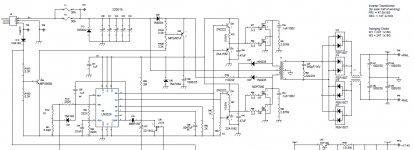
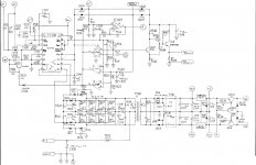
ok i let it idle and after about 30 seconds the voltage regulator LM337T got real hot.
looking at my burn mark it looks like leg 1 and 2- or -2 and 3 got vary hot.
I replaced that one with LM337TFS-ND NEG ADJ 1.5 TO 220 the new chip had a thin back plate. my old lm337t leg 1 to 3 =12.95m ohm's and dropping leg 1 to 2 =0 leg 2 to 3 2.400m ohm's.
looking at my burn mark it looks like leg 1 and 2- or -2 and 3 got vary hot.
I replaced that one with LM337TFS-ND NEG ADJ 1.5 TO 220 the new chip had a thin back plate. my old lm337t leg 1 to 3 =12.95m ohm's and dropping leg 1 to 2 =0 leg 2 to 3 2.400m ohm's.
ok i get sound out of both channels, the resistor fixed the hot chip 337t.
it does not get hot at idle.
bridged seem to work ( i did not test it long)
the amp got hot enough to were I cant hold it after i tested it with music.(i don't know if thats normal?)
the sound does not seem to be clear at times?
and no light on the led? had light last knight.
ill let it cool down then ill test the bridged mode.
It's normal for amplifiers like this to get too hot to touch. They will heat up more quickly when driven hard into lower impedance loads.
The LED operates off of the regulated power supply. There may be a broken trace. If the voltage on the output of the regulator went to full rail voltage when the resistor was missing, the LED may have burned out. You should read ~1.5-2v across the LED. If it's significantly higher or lower, the LED is likely defective.
The LED operates off of the regulated power supply. There may be a broken trace. If the voltage on the output of the regulator went to full rail voltage when the resistor was missing, the LED may have burned out. You should read ~1.5-2v across the LED. If it's significantly higher or lower, the LED is likely defective.
What size fuse did you have in the amp?
Was it blown?
Did you replace the heatsink compound each time you reassembled the amp?
What heat source did you use to solder the transistors to the MEHSA insulators?
Did you tin the back of the transistors before soldering them to the MEHSA strip?
Was it blown?
Did you replace the heatsink compound each time you reassembled the amp?
What heat source did you use to solder the transistors to the MEHSA insulators?
Did you tin the back of the transistors before soldering them to the MEHSA strip?
I don't mean to butt-in, but just a couple things i would like to add. one thing i have noticed in just about all of these line of amps i've run across the table, is that they all benefit, or require a bias adjustment. i'm sure it is not what is wrong, but, especially with brand new outputs, i would do it just as soon as it is idling well.
second: if your fluke has a hz button, i have used that to see that the power fets are being switched, and at what duty cycle. it doesn't sound like you have a scope, and it may help.
carry on.. /$.02
second: if your fluke has a hz button, i have used that to see that the power fets are being switched, and at what duty cycle. it doesn't sound like you have a scope, and it may help.
carry on.. /$.02
there was a 30 amp fuse with#8 wire- yes its blown ( gold plated fuse)
I used new heat sink compound 276-1372 silicone base heat sink radioshack brand.
I used a small butane torch (harbor freight brand)- with the chip about 1/8 from the mehsa board I waited for the solder to melt then i clamped them with binder clip to the board. ( it took a few tries)
tinning 3205 was easy. (it had a dull backing) the 9540,540 on the other hand was quit hard as it had a shinny back and the solder would just roll off or bead.( i could not get a complete tin on those chips just the upper half) but they looked good after i was done.
I have enough chips left over to replace all the damaged chips, so ill do it again.
When tinning the backs of the transistors with the mirror-finish tabs, sand the tab until it's dull. It will take solder a lot more readily. When you have to apply heat for a longer period of time, there is a greater risk of damaging the transistors.
As was suggested, you need to bias the transistors. If you have a power supply with an amp meter, set it as is shown in the following demo.
http://www.bcae1.com/temp/ausettingbias.swf
If you don't have an amp meter on the power supply, set the bias by using the DC voltage across the emitter resistors. Set the bias so that you have approximately 0.001v across the emitter resistors at idle.
I removed the board, on the back of the board, were the 3205 chips are, the
middle leg of the 3205 going to the tall resistor- it pealed off the green so copper is showing. it looks like it broke its link to the 63v 330uf resistor.
more heat on the right, less so on the left.
looking at the side were the 9540 and 540 shorted, i did not get a good weld.
middle leg of the 3205 going to the tall resistor- it pealed off the green so copper is showing. it looks like it broke its link to the 63v 330uf resistor.
more heat on the right, less so on the left.
looking at the side were the 9540 and 540 shorted, i did not get a good weld.
ok replaced bad chips.
in idle it stayed cool, the led light works now.
on the fet gate leg I got 9.4 on both.
when i tested it for sound both left and right side, all i got was thud thud thud?
with the bass boost turned down I can hear sound out of the sub but it sounded like a high frequency tweeter cracking.
in idle it stayed cool, the led light works now.
on the fet gate leg I got 9.4 on both.
when i tested it for sound both left and right side, all i got was thud thud thud?
with the bass boost turned down I can hear sound out of the sub but it sounded like a high frequency tweeter cracking.
Thanks Perry I needed that.When tinning the backs of the transistors with the mirror-finish tabs, sand the tab until it's dull. It will take solder a lot more readily. When you have to apply heat for a longer period of time, there is a greater risk of damaging the transistors.
As was suggested, you need to bias the transistors. If you have a power supply with an amp meter, set it as is shown in the following demo.
http://www.bcae1.com/temp/ausettingbias.swf
If you don't have an amp meter on the power supply, set the bias by using the DC voltage across the emitter resistors. Set the bias so that you have approximately 0.001v across the emitter resistors at idle.
- Status
- This old topic is closed. If you want to reopen this topic, contact a moderator using the "Report Post" button.
- Home
- General Interest
- Car Audio
- rock fosgate 250 a2 help.

